Refiner disc and method

a refiner disc and disc body technology, applied in the field of refiner discs, can solve the problems of unidirectional edge wear of commercial refiner discs, affecting reducing pulp quality and efficiency, so as to reduce refiner wear and refiner disc wear, reduce the magnitude or amplitude of refiner loads, and increase the load and throughput

Inactive Publication Date: 2001-12-04
J & L FIBER SERVICES
View PDF34 Cites 48 Cited by
  • Summary
  • Abstract
  • Description
  • Claims
  • Application Information

AI Technical Summary

Benefits of technology

It is another object of the present invention to permit the refiner to operate under greater load and throughput than previously achieved in refiners using prior art refiner discs.
It is an advantage of the present invention that the magnitude or amplitude of refiner loads are reduced by at least 40% by using a segmented refiner disc of the invention having at least four fields per segment as compared to a conventional segmented refiner disc of the same angular extent having only two radial fields.
It is another advantage of the present invention that refiner wear and refiner disc wear is reduced by using a refiner disc having radial fields with a maximum angular extent no greater than 30.degree. because vibration and loading is reduced.
It is still another advantage of the present invention that the gap between opposed refiner disc varies less because vibration and load are less and because steam flows more easily from out between the discs.
It is an additional advantage of the present invention that the duration and magnitude of the load swing and associated cycling is reduced by at least 40% and preferably by over half.
Other objects, features, and advantages of the present invention are to provide a refiner disc that can be of segmented construction; which is capable of bi-directional operation; which can easily be mounted and removed; which can be cast along with all fields and bars in a single operation; does not require fabrication; and is rugged, simple, flexible, reliable, and durable, and is of economical manufacture, and is easy to assemble and simple to use.

Problems solved by technology

Many commercial refiner discs are unidirectional, that is, designed to be rotated only in one direction, or to be stationary and oppose a refiner disc that is rotated only in one direction.
As a result, the leading edge of each bar wears much more quickly than the trailing edge.
When too much wear occurs, pulp quality and efficiency dramatically decrease until the refiner disc must be replaced.
When unidirectional discs are reversed, which inevitably happens, refining costs rise because refining quality and efficiency suffer.
Moreover, rotating a unidirectional disc the wrong direction in secondary or rejects refining applications reduces throughput and efficiency and can destroy fiber strength.
When a hold back cycle begins, the radial outward flow of the fiber is drastically disrupted causing a great deal of the momentum of the stock to be absorbed by the refiner.
This results in an increasing load, L.sub.1 (FIG. 3), on the refiner that has a particular amplitude that builds over time until it reaches amplitude, P.sub.1.
These load swings cause vibration that significantly impacts refiner operation.
First, the refiner operates less efficiently than desired.
Second, pulp quality can undesirably vary.
Third, wear is accelerated on the components of the refiner, as well as the refiner disc itself.
Unfortunately, this can impede outward flow of the stock, which can reduce refiner throughput.
Unfortunately, too many dams can obstruct steam flow through the disc.
Not only can obstructed steam impede the outward flow of the stock, it can also backflow steam into the stock being fed into the refiner thereby reducing the infeed rate.
Moreover, the vibration in combination with obstructed steam can lead to variations in the refining gap, which can further reduce the consistency of pulp quality.

Method used


Image

  • Refiner disc and method
  • Refiner disc and method
  • Refiner disc and method

Examples


Embodiment Construction

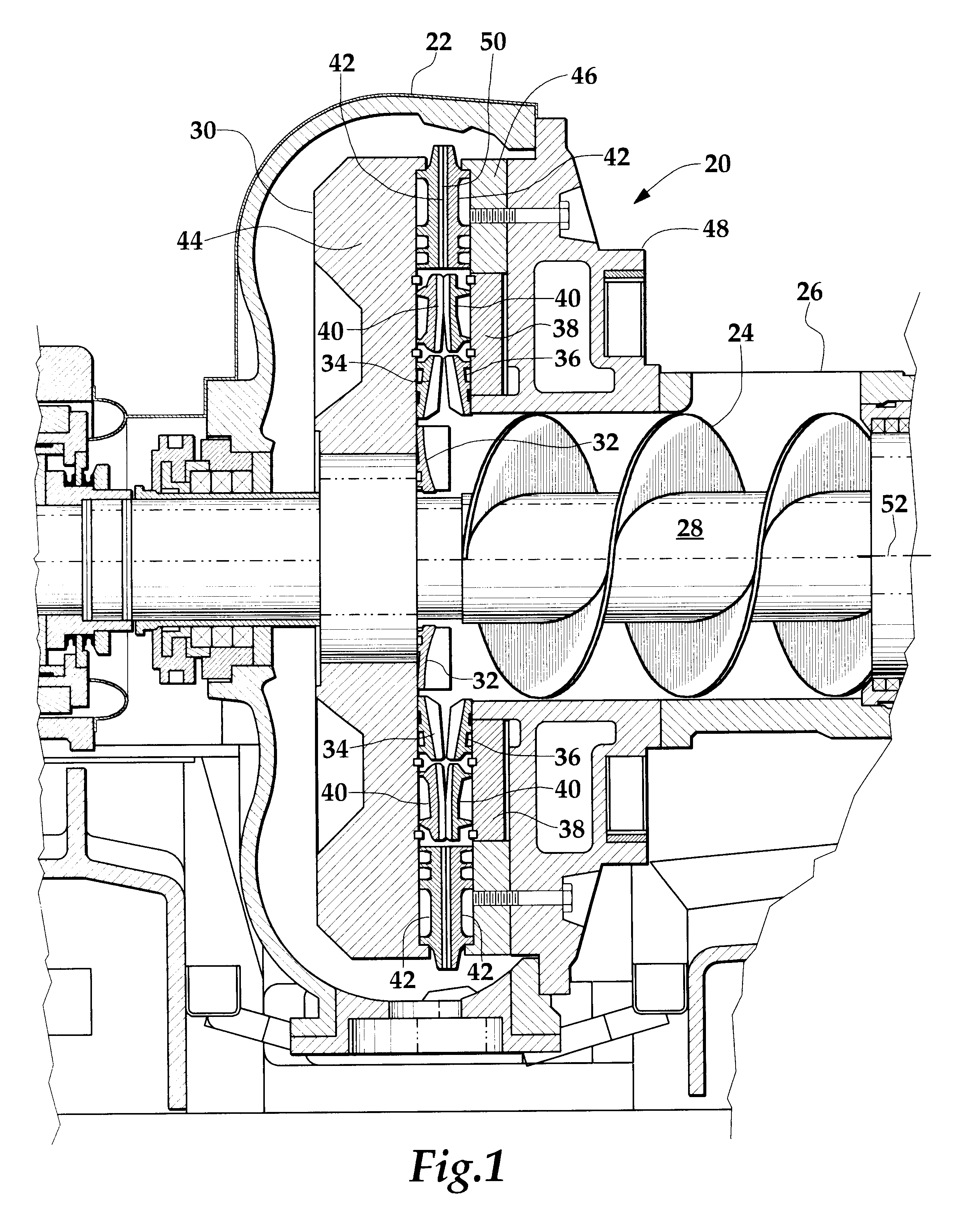
An exemplary refiner 20 is shown FIG. 1. The refiner 20 has a housing 22 and an auger 24 mounted therein which urges a stock slurry of liquid and fiber introduced through a stock inlet 26 into the refiner 20. The auger 24 is carried by a shaft 28 that rotates during refiner operation to help supply stock to an arrangement of treating structure within the housing 22 and a rotating rotor 30. An annular flinger nut 32 is generally in line with the auger 24 and directs the stock radially outwardly to a plurality of opposed sets of breaker bar segments 34 and 36.

Each set of breaker bar segments 34 and 36 preferably are in the form of sectors of an annulus, which together form an encircling section of breaker bars. One set of breaker bar segments 34 is fixed to the rotor 30. The other set of breaker bar segments 36 is fixed to another portion of the refiner, such as a stationary mounting surface 38 of the housing 22 or another rotor (not shown).

The breaker bar segments 34 and 36 discharge...


PUM

PropertyMeasurementUnit
angleaaaaaaaaaa
angleaaaaaaaaaa
angleaaaaaaaaaa

Abstract

A refiner disc and segment for a rotary disc fiber refiner which has a plurality of radial fields each having an angular extent no greater than 30° and preferably no greater than 22° for reducing the amplitude and duration of load swings that take place during pumping and holdback cycles. Each field has a refining zone with a refiner groove and a refiner bar and a second zone disposed radially outwardly of the refining zone that changes the direction of flow of stock to reduce stock flow momentum and magnitude of the load swings. Each field can have a third zone radially outward of the second zone that further changes the direction of flow of stock and an infeed zone radially inwardly of the refining zone. If desired, a zone that includes a breaker bar can be disposed radially inwardly of the infeed zone. Where the disc is segmented, the segment has at least three fields. In one preferred embodiment, the segment has at least four fields which reduces the duration and magnitude of load swings by at least 40% thereby reducing refiner vibration and wear while advantageously increasing consistency of pulp quality and throughput. The disc and segment are capable of bi-directional operation without loss of efficiency, quality, and throughput.

Description

This invention relates to refiners which prepare fibers for use in paper-based products including papermaking, to rotary disc refiners in particular, and to a refiner disc and method of refining using a refiner disc that is capable of bi-directional operation.For papermaking purposes, wood chips, or another fiber source, are ground into smaller chips, or mechanically treated, so that the chips may be broken down further and refined preferably into individual fibers. After refining, these individual fibers are used to make paper or paper-related products, such as paper cups, paper plates, toilet paper, paper towels, diapers, and other products that can be absorbent.Disc refiners are used to break down clumps of fibers into individual fibers. A disc refiner typically utilizes pairs of opposed refiner discs. A refiner disc is a disc-shaped steel or steel-alloy casting, which has an array of generally radially extending bars or upraised ridges formed in its refining face or refining sur...

Claims


Application Information

Patent Timeline
Patent Type & Authority Patents(United States)
IPC IPC(8): B02C7/12B02C7/00D21D1/30D21D1/00
CPCB02C7/12D21D1/306
Inventor LOFGREN, MATTIASHOLLAND, CHRISTOPHER M.
Owner J & L FIBER SERVICES
Why Eureka
Try Eureka