Method for load control using temporal measurements of energy for individual pieces of equipment

a technology of energy measurement and load control, applied in the integration of power network operation systems, process and machine control, instruments, etc., can solve the problems of short-term deployment of a measuring capability, inability to provide an indication of usage patterns at the equipment level, and inability to provide energy measurement at the premise level, so as to improve the efficiency of load control operation.

Active Publication Date: 2010-03-18
ACLARA TECH LLC
View PDF36 Cites 67 Cited by
  • Summary
  • Abstract
  • Description
  • Claims
  • Application Information

AI Technical Summary

Benefits of technology

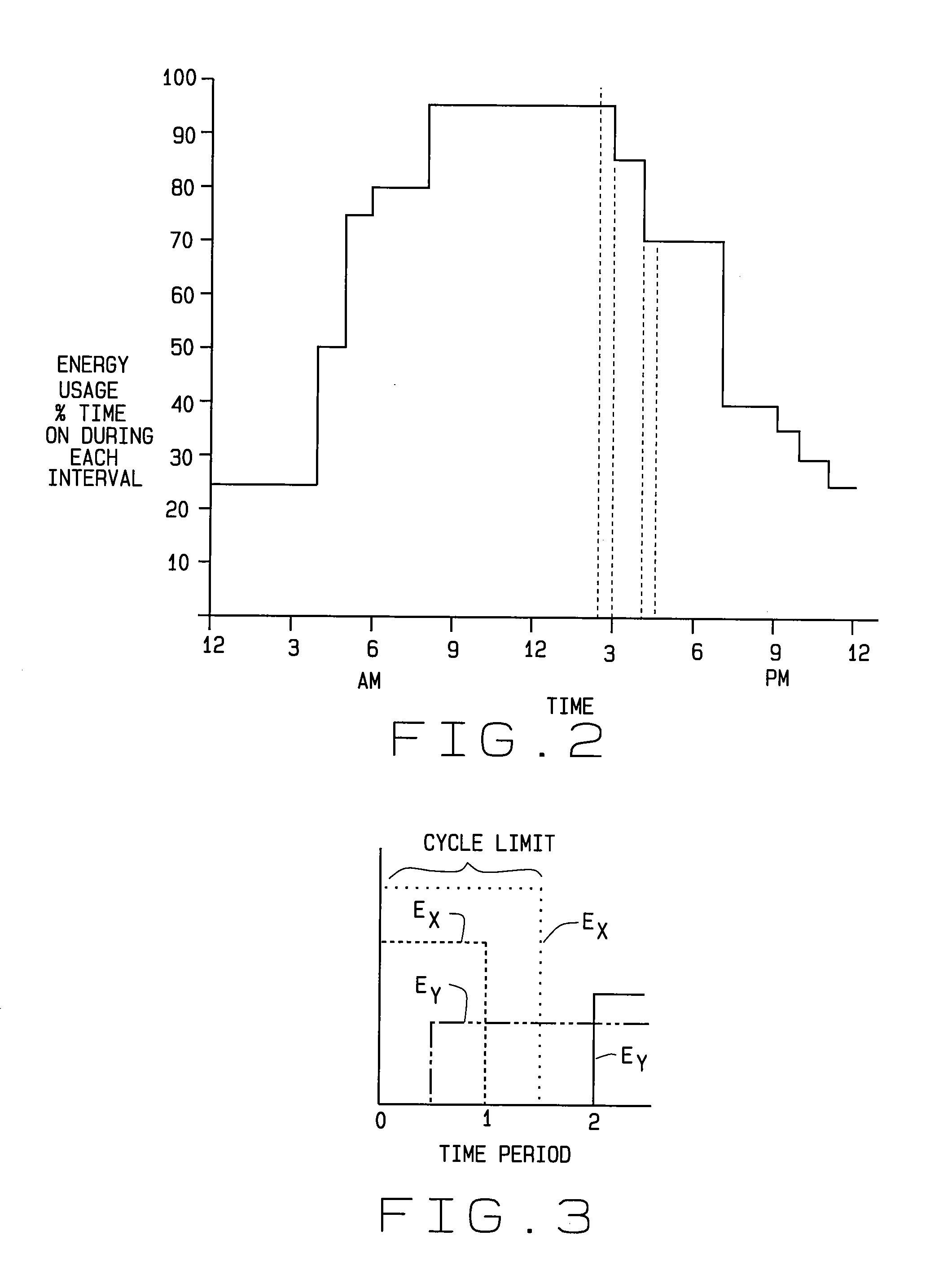
[0021]The LCU employed with the method of the invention tries to optimize load shedding by a piece of equipment, and in doing so, attempts to ensure a reasonable match between the equipment's usage profile and its actual behavior during a load control event. Doing so enhances the efficiency of the load control operation. That is, a piece of equipment's usage profile can provide information as to when the equipment will be energized, indicating a need for electrical energy. At such time, and in accordance with the method of the invention, the LCU to which the equipment is connected allows the equipment to run for a predetermined period of time. When this time expires, the LCU interrupts supply of power to the equipment and load is shed. This interruption lasts for an amount of “shed time” based on the usage profile for the piece of equipment and the amount of load reduction desired. After this “shed time” has passed, power can again be supplied to the equipment (if the equipment is to be powered at this time); and, if powered, the equipment is allowed to run for a new, adjusted run time, again presenting a load to the system. This cycling process continues for the duration of the load control event.

Problems solved by technology

Directly measuring energy usage, however, has a number of drawbacks.
While some utilities may only employ demand measuring capability for a short time, i.e., until robust models are developed, even the short term deployment of a measuring capability may not only be cost prohibitive, but also require additional levels of system management.
Also, measuring usage at the premise level does not provide an indication of usage patterns at the equipment level.
Accordingly, it is desirable to profile equipment energy usage in a way that does not incur the extra cost and / or complexity of load demand metering while not reducing the effectiveness of control.
That is, these methods have no mechanism which ensures that a piece of equipment (the “load”) actually needs power at a time when a load control event is occurring.
A method which attempts to determine or set the power requirement for equipment during a load control event is therefore imposing an artificial burden on the system.
In effect, in these prior load control systems, the control signal only sets an upper limit of usage on the equipment.
However, many loads are driven only on a time basis, or by some other mechanism, that does not “self-synchronize” with load control signals.
The latter method does not give a measure of effectiveness straight away.
Even load control methods employing sophisticated models have an operational disadvantage because of the number of computations needed to provide meaningful feedback to a utility.
In addition to the complexities inherent in the modeling, the resulting models do not necessarily reflect the fact that a given consumer might suffer from, for example, air-conditioner under-capacity.
What might appear from the utility's perspective to be a very good load to shed because it runs all of the time, might be from the customer's perspective a very bad load to shed because it needs to run all of the time.
The customer may, for example, experience undue discomfort when the program is executed, and opt out of the program, which is not a favorable result for the utility.
This increased demand is counter-productive to the original need for load control.
Indeed, if the need for load control was triggered by a reliability concern, then this increase in demand may retrigger the event and load control will start over again.

Method used


Image

  • Method for load control using temporal measurements of energy for individual pieces of equipment
  • Method for load control using temporal measurements of energy for individual pieces of equipment
  • Method for load control using temporal measurements of energy for individual pieces of equipment

Examples


Embodiment Construction

[0030]The following detailed description illustrates the invention by way of example and not by way of limitation. This description clearly enables one skilled in the art to make and use the invention, and describes several embodiments, adaptations, variations, alternatives and uses of the invention, including what is presently believed to be the best mode of carrying out the invention. Additionally, it is to be understood that the invention is not limited in its application to the details of construction and the arrangement of components set forth in the following description or illustrated in the drawings. The invention is capable of other embodiments and of being practiced or carried out in various ways. Also, it will be understood that the phraseology and terminology used herein is for the purpose of description and should not be regarded as limiting.

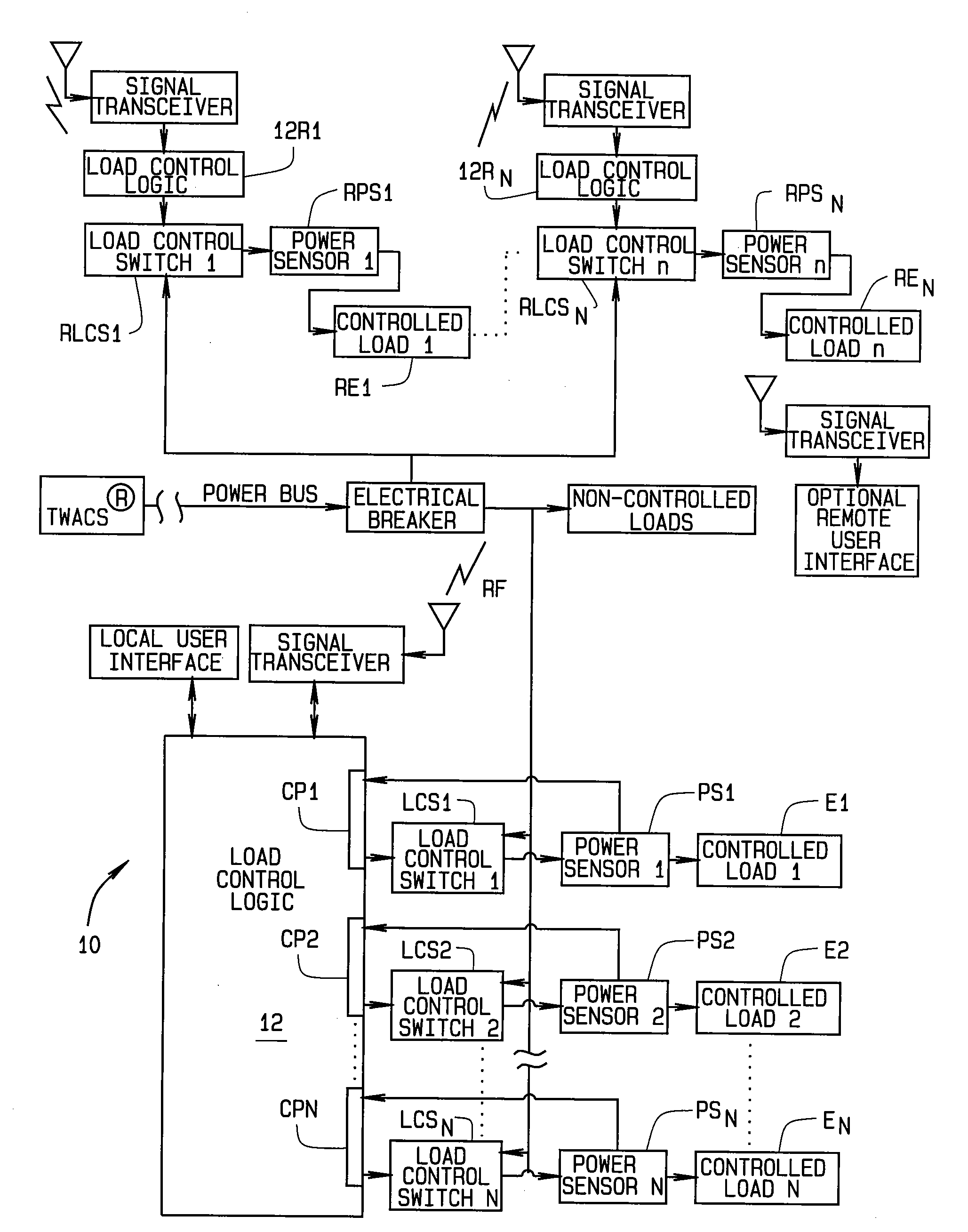
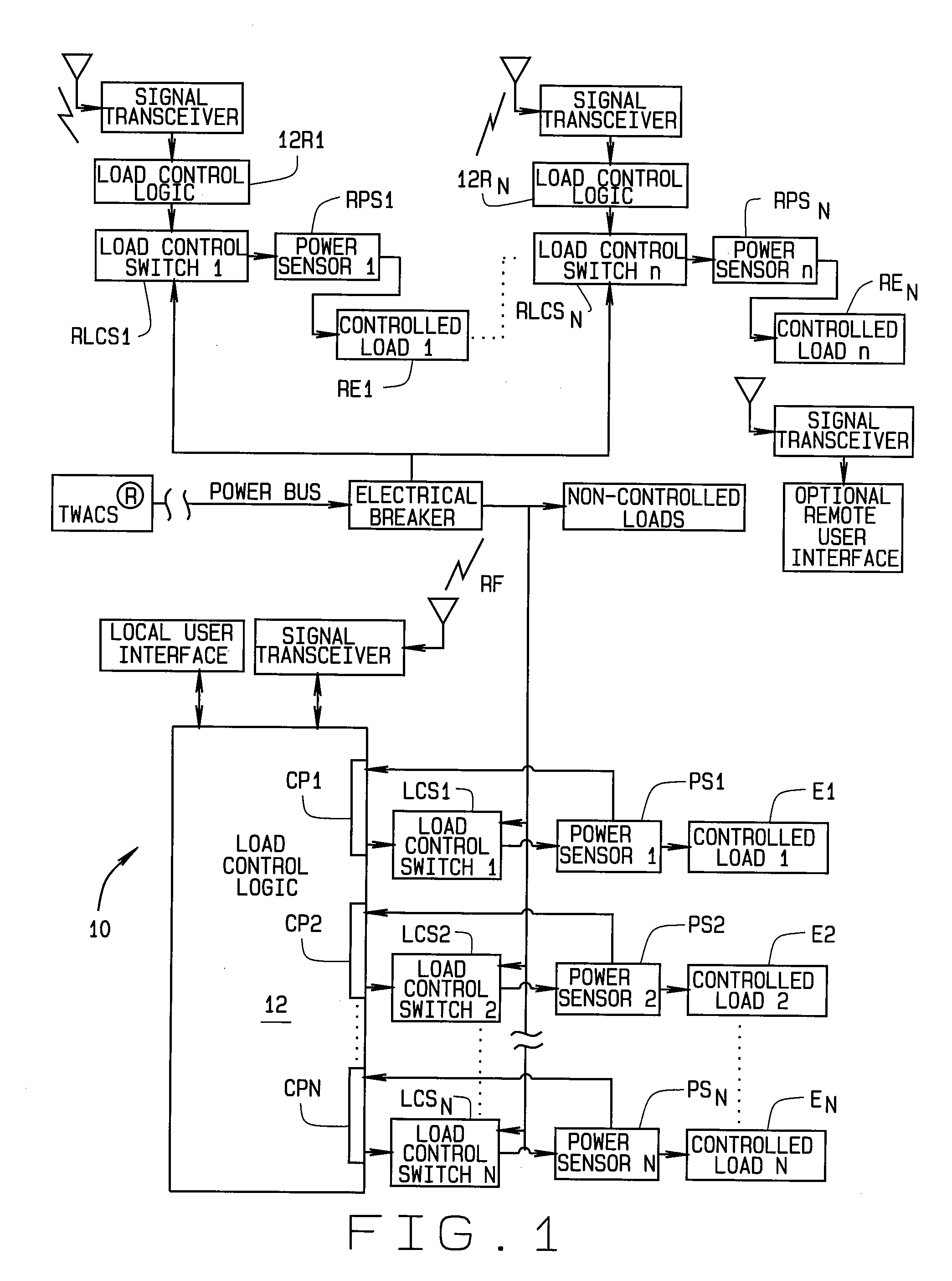
[0031]Referring to FIG. 1, a load control unit or LCU generally indicated 10 is installed at a customer's site. The LCU is attache...


PUM


Abstract

A method for load control in an electrical distribution system using energy usage profiles based on temporal measurements. A load control unit (10) installed at a customer site profiles equipment (E1-En) directly connected to the load control unit and remotely located equipment (RE1-REn) wirelessly connected to the load control unit using measurements of time rather than energy usage. This reduces the cost and complexity of the load control unit. Profiling is done for individual pieces of load controlled equipment rather than for the site as a whole. This improves data resolution. The load control unit controls the load only when the equipment is powered, and adaptively synchronizes load shedding during this time, so to improve local load control performance. Termination of a load control event results in gradual reduction in load shedding so to control the inrush of demand seen by the distribution system. Performance metrics related to the load control are provided to the utility such that complexity of the system is reduced through decreased computations.

Description

CROSS-REFERENCE TO RELATED APPLICATIONS[0001]The present application is related to and claims priority from, U.S. provisional patent application 61 / 097,040 filed Sep. 15, 2008, which is incorporated herein by reference.STATEMENT REGARDING FEDERALLY SPONSORED RESEARCH[0002]Not Applicable.BACKGROUND OF THE INVENTION[0003]This invention relates to load control in an electrical distribution system; and, more particularly, to a method of performing load control using temporal measurements of energy usage by individual pieces of equipment connected to the system.[0004]Electrical utilities must continually manage their capacity to ensure that the amount of electricity generated by the utility, or purchased from other utilities, is sufficient to meet the load demand placed on the system by their customers. Utilities generally have two options for meeting demands on the system during periods of peak energy demand (loading). These include either bringing additional generating capacity on-line...

Claims


Application Information

Patent Timeline
Patent Type & Authority Applications(United States)
IPC IPC(8): G06F1/28
CPCH02J3/14Y04S20/222Y02B70/3225H02J2310/60H02J2310/54
Inventor FLECK, CHRISTOPHER K.KOBESZKA, EDWARDVIRKUS, MARK
Owner ACLARA TECH LLC
Why Eureka
Try Eureka