Load cell

a technology of load cell and stopper, which is applied in the direction of force/torque/work measurement apparatus, weighing apparatus details, instruments, etc., can solve the problems of long development period, low development efficiency, and increase in the number of stoppers, so as to achieve the effect of elevating the development efficiency of the load cell

Active Publication Date: 2015-10-08
A&D CO LTD
View PDF4 Cites 4 Cited by
  • Summary
  • Abstract
  • Description
  • Claims
  • Application Information

AI Technical Summary

Benefits of technology

[0034]In accordance with the load cell of the present invention, the excessive deformation of the thin portions due to the overload in the torsion direction exerted on the flexural element can be prevented without fail for a longer period of time because the front portion of the stopper for preventing the overload projects toward the outside in the direction of the movable portion, further the assembling of the load cell can be easily conducted by utilizing the outward projecting part of the movable portion of the front portion of the stopper, and still further, the development efficiency of the load cell can be elevated because the clearance can be determined only by the shape of the load cell.

Problems solved by technology

In case of separate stoppers, the stopper is required for each type of the stoppers so that a problem arises that the number of the stoppers increases.
Accordingly, there arises a defect that a long period of development is required and a development efficiency is low.
The separate stopper includes a defect of not completely preventing of the overload delivered to the load cell because of the deformation of the supporting member for the load cell during the overload.

Method used


Image

  • Load cell
  • Load cell
  • Load cell

Examples


first embodiment

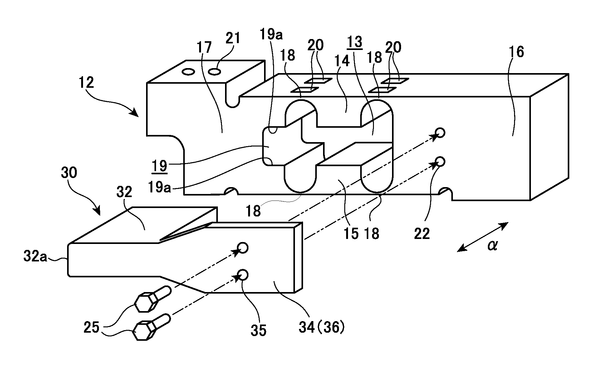
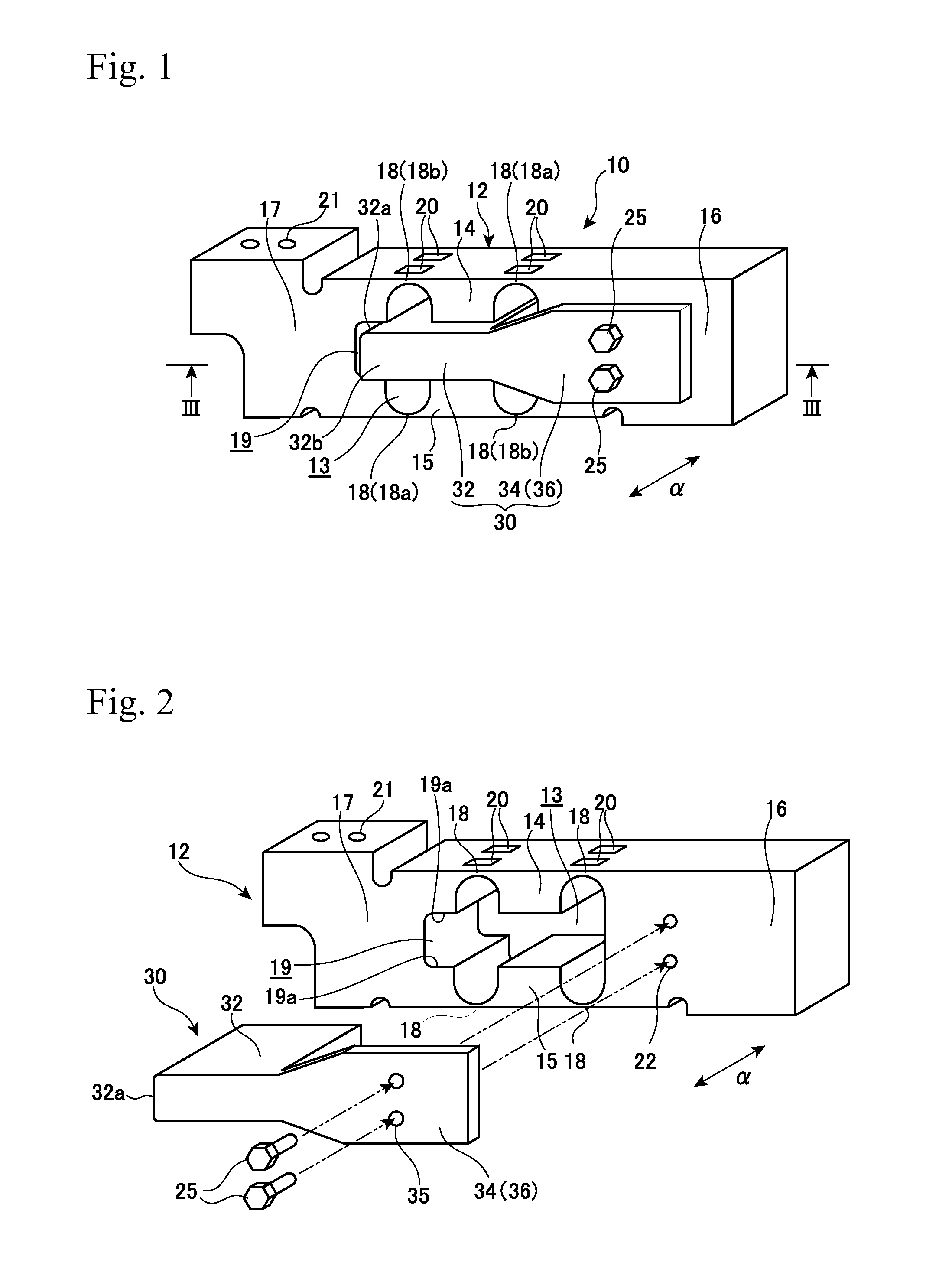
[0048]Preferable embodiments of the present invention for the load cell will be described referring to the annexed drawings. FIG. 1 is a perspective view showing a load cell 10 of a first embodiment to which the present invention is applied, FIG. 2 is an exploded perspective view of the load cell 10, and FIG. 3 is a sectional view taken along a line III-III of FIG. 1.

[0049]As shown in these drawings, the load cell 10 mainly includes a flexural element 12, strain gauges 20 and a stopper 30 for preventing an overload.

[0050]The flexure elements 12 is composed of a metal such as aluminum, and is produced, for example, by cutting, with a constant width, the metal having a specified shape prepared by extrusion molding, if necessary, followed by a cutting operation. A penetration aperture 13 in the shape of nearly eyeglasses is formed through the flexural element 12 in the width direction (direction of arrow α). The formation of this penetration aperture 13 provides the flexure element 12 ...

second embodiment

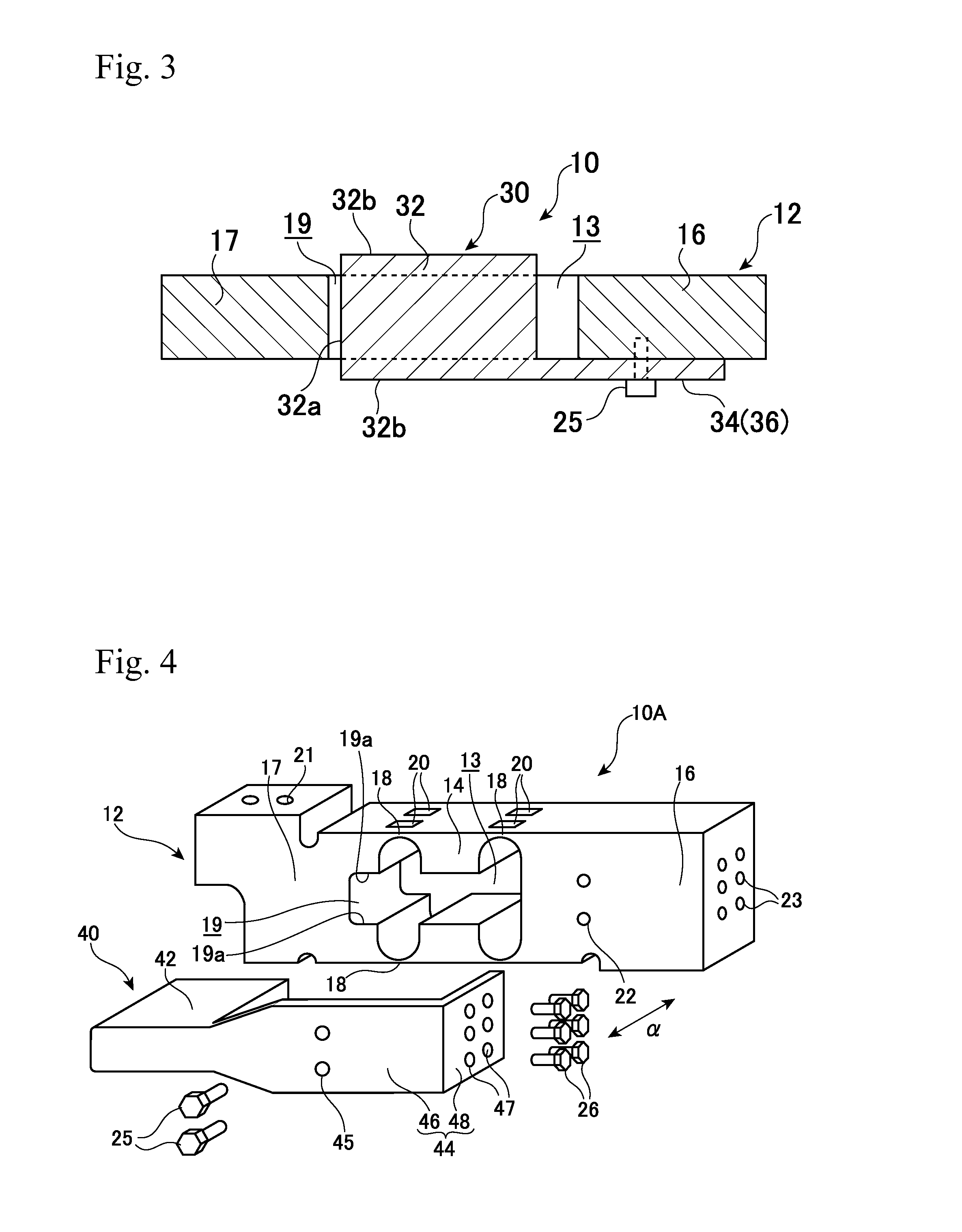
[0063]FIG. 4 is an exploded perspective view of a load cell 10A of a second embodiment, and FIG. 5 is a horizontal sectional view of the load cell 10A near the center thereof (the section at the same position as that of FIG. 3).

[0064]In the load cell 10A of the second embodiment, only the shape of a stopper 40 is different from the load cell 10 of the first embodiment, and the other components are same as those of the load cell 10. Accordingly, the stopper 40 having the different configuration will be described in detail, and the description of the components having similar configurations and performances to those of the load cell 10 will be omitted by attaching the same symbols thereto.

[0065]The stopper 40 of the second embodiment differs from the stopper 30 of the first embodiment in that an end plate portion 48 is formed.

[0066]The stopper 40 is composed of a front portion 42 and a base portion 44 integrated with each other, and the front portion 42 is formed broader than the mova...

third embodiment

[0078]In the stopper 50 of the third embodiment having the above configuration, the entire width of the front portions 52X, 52Y integrally connected is larger than the width of the movable portion 17. Accordingly, similarly to the preceding embodiments, the loading of an overload in the torsion direction can be prevented without fail.

[0079]The stronger fixation can be obtained in the stopper 50 of the third embodiment because the separate stoppers 50X, 50Y are fixed such that they sandwich the fixed portion 16 from the both sides in its width direction.


PUM

PropertyMeasurementUnit
widthaaaaaaaaaa
heightaaaaaaaaaa
tensionaaaaaaaaaa

Abstract

A load cell includes a flexure element having a Roberval mechanism in which the respective ends of a pair of top and bottom parallel beams including a thin section are integrated in a fixed portion and in a movable portion, and a stopper for preventing an overload disposed between the pair of the top and bottom parallel beams by being fixed to the fixed portion. The front portion of the stopper is disposed in a concave portion for engaging the stopper formed on the inner side surface of the movable portion and extending in the width direction, and the front portion of the stopper of which a width is larger than the movable portion projects outwardly in the width direction of the movable portion.

Description

TECHNICAL FIELD[0001]The present invention relates to a load cell, and, especially, relates to a Roberval load cell, which includes a built-in stopper for preventing an overload.BACKGROUND ART[0002]A Roberval load cell is used for, for example, a balance for commerce and industry, and includes a flexure element having four thin parts in all which are composed of a top pair and a bottom pair each having two thin parts. The base part of the flexure element is fixed in a cantilever manner, and the top part is applied with a load. Two thin parts out of the four parts act as tension sides and another two parts act as compression sides. Strain gauges are bonded to each of the thin parts of the tension sides and of the compression sides. The four strain gages are connected with one another to constitute the Wheatstone bridge.[0003]In the load cell having such configuration, a stopper for preventing the overload is mounted for preventing the excessive deformation of the thin parts during th...

Claims


Application Information

Patent Timeline
Patent Type & Authority Applications(United States)
IPC IPC(8): G01L1/26G01L1/22
CPCG01L1/2206G01L1/26G01L1/2243G01G23/005
Inventor SATO, ISAO
Owner A&D CO LTD
Why Eureka
Try Eureka