Heat sink assembly and clip thereof

a technology of heat sink and assembly, which is applied in the direction of couplings, manufacturing tools, lighting and heating apparatus, etc., can solve the problems of difficult installation of movable fasteners passing through through holes, complicated installation process of conventional clips, and complicated installation process of entire installations, so as to reduce the heat generated by electronic devices and simplify the installation procedure.

Active Publication Date: 2014-09-18
DELTA ELECTRONICS INC
View PDF6 Cites 6 Cited by
  • Summary
  • Abstract
  • Description
  • Claims
  • Application Information

AI Technical Summary

Benefits of technology

[0016]As mentioned above, the clip of the invention can fix the heat sink on the retaining bracket and press the heat sink closer to the electronic device so as to dissipate the heat generated by the electronic device more effectively. The clip has an operating member pivoting to the connecting portion, a movable fastener installed on the resisting portion and the connecting portion, and a fixing bar inserted into the sliding slots of the movable fastener. Accordingly, the installation procedure of the clip of the invention is much simpl

Problems solved by technology

However, the conventional clip has a very complicated installation procedure.
The installation of the movable fastener passing through the through holes is difficult.
This procedure needs two steps to mount the protrusions, so the entir

Method used


Image

  • Heat sink assembly and clip thereof
  • Heat sink assembly and clip thereof
  • Heat sink assembly and clip thereof

Examples


Embodiment Construction

[0025]The present invention will be apparent from the following detailed description, which proceeds with reference to the accompanying drawings, wherein the same references relate to the same elements.

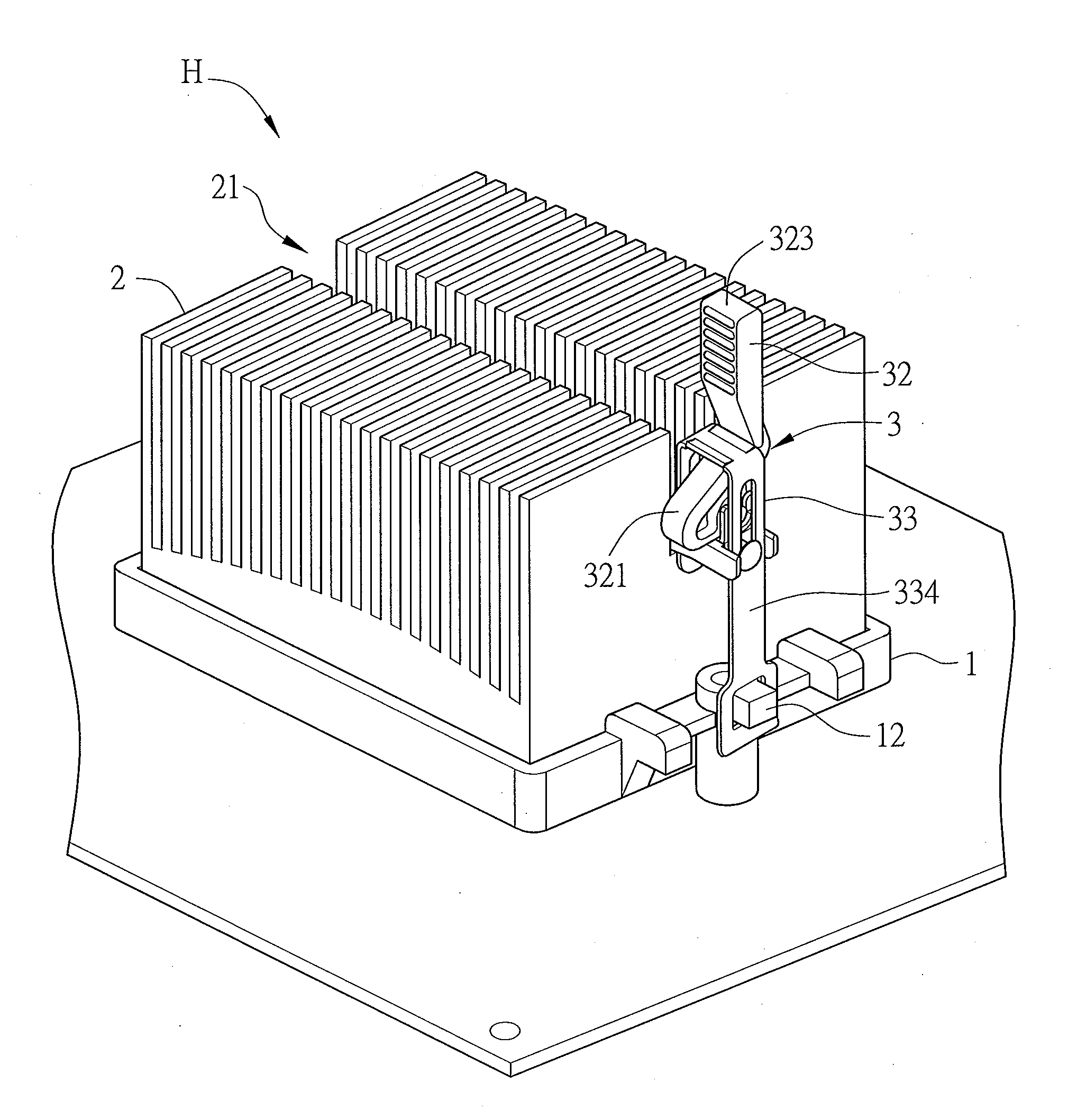
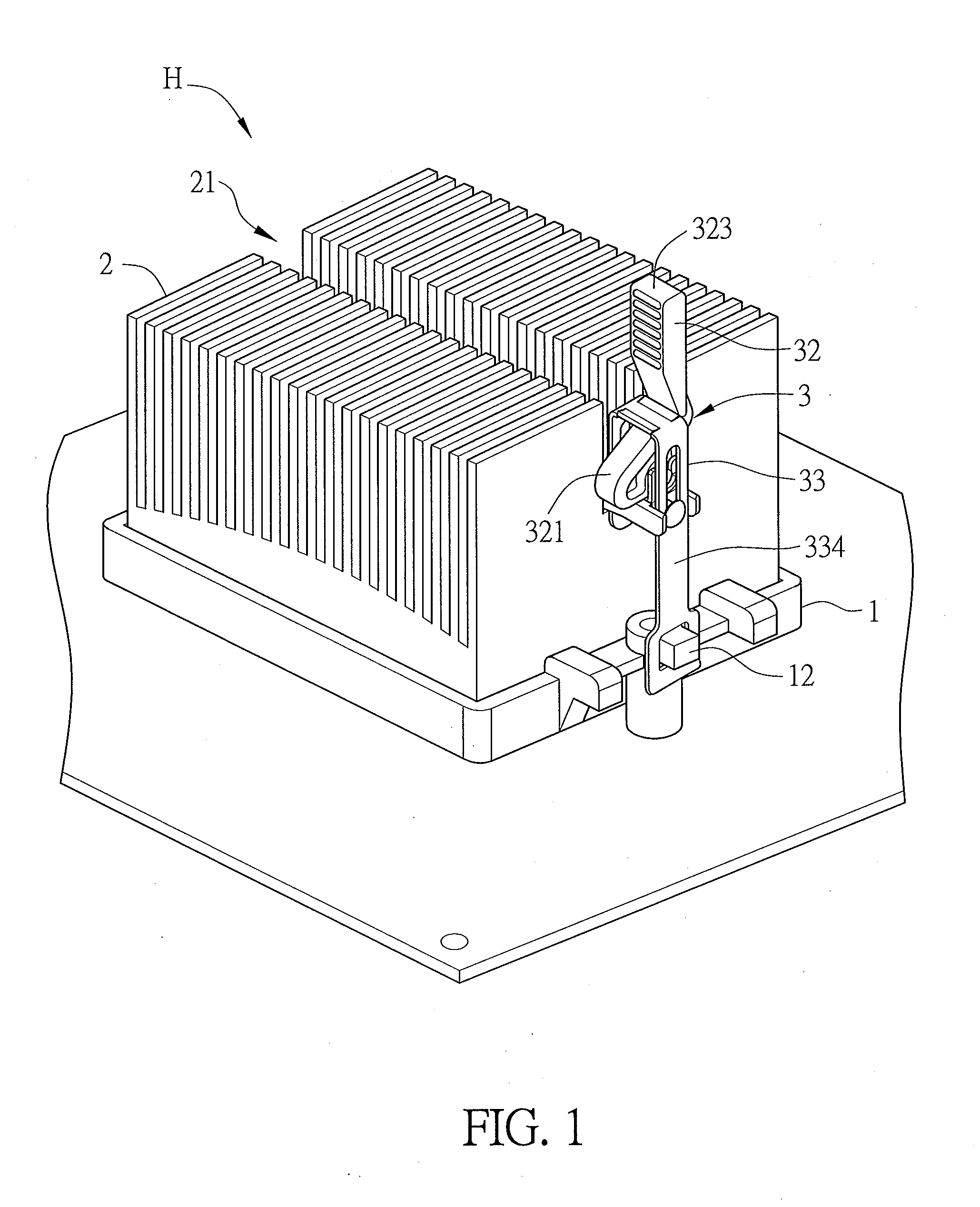
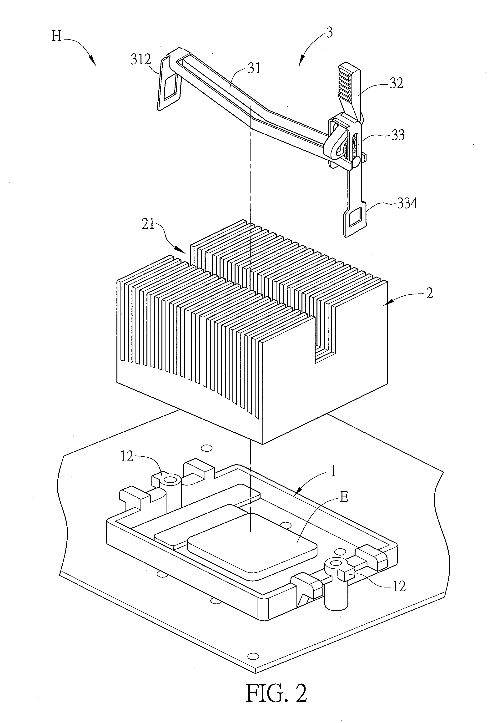
[0026]FIG. 1 is a perspective diagram showing a heat sink assembly H according to an embodiment of the present invention, and FIG. 2 is an exploded view of the heat sink assembly H. Referring to FIGS. 1 and 2, the heat sink assembly H is used for dissipating the heat generated by an electronic device E, and includes a retaining bracket 1, a heat sink 2, and a clip 3. The retaining bracket 1 is disposed at the periphery of the electronic device E, and the heat sink 2 is disposed corresponding to the retaining bracket 1 and the electronic device E. Preferably, the retaining bracket 1 surrounds the electronic device E, and the shape of the retaining bracket 1 fits the structure of the heat sink 2. Accordingly, the heat sink 2 can be accommodated on the retaining bracket 1 and thus dispos...


PUM


Abstract

A clip for fixing a heat sink on a retaining bracket includes an elastic supporter, an operating member, a movable fastener and a fixing bar. Two ends of the elastic supporter have a connecting portion and a first buckle portion, respectively. The operating member has a resisting portion, a pivot portion and an operating bar. The pivot portion pivots to the connecting portion. The movable fastener installs on the resisting portion and the connecting portion, and includes two sliding slots, a resisting surface and a second buckle portion. The resisting portion has an arc surface for resisting against the resisting surface. The distance between the apex of the arc surface and the pivot portion is the largest distance between the arc surface and the pivot portion. When the clip is locked, the junction of the resisting portion and the resisting surface excludes the apex of the arc surface.

Description

CROSS REFERENCE TO RELATED APPLICATIONS[0001]This Non-provisional application claims priority under 35 U.S.C. §119(a) on Patent Application No(s). 201310085115.0 filed in People's Republic of China on Mar. 15, 2013, the entire contents of which are hereby incorporated by reference.BACKGROUND OF THE INVENTION[0002]1. Field of Invention[0003]The present invention relates to a heat sink assembly and clip thereof.[0004]2. Related Art[0005]Due to the rapid progress of electronic industry, the electronic modules, such as the CPU, have been greatly improved. Accompanying the improved performance of the CPU, the generated heat is increased. In order to effectively remove the heat generated by the electronic module, a heat sink is commonly disposed adjacent to the CPU or other electronic modules for rapidly taking the heat away. Thus, the CPU or electronic module can operate at the normal working temperature so as to extend the lifespan of the products.[0006]In order to make the heat sink cl...

Claims


Application Information

Patent Timeline
IPC IPC(8): F16B2/22
CPCF16B2/22F16B2/08Y10T403/595H01L23/4093
Inventor LIN, YU-HSIENTAN, LI-KUANG
Owner DELTA ELECTRONICS INC
Why Eureka
Try Eureka