Removable Apparatus To Regulate Flame Heat Transfer And Retain Dripping Liquid Substance For A Gas Stove Burner

a technology of flame heat transfer and removable apparatus, which is applied in the field of gas stove accessories, can solve the problems of consuming a large amount of combustible gases in the use of gas stoves, and achieve the effects of preventing undesirable heating of the handle of the utensil in cooking, facilitating the cleaning of the stove cooktop, and increasing heating efficiency

Active Publication Date: 2014-12-18
SUN YIZHONG
View PDF9 Cites 1 Cited by
  • Summary
  • Abstract
  • Description
  • Claims
  • Application Information

AI Technical Summary

Benefits of technology

[0021]Both the inner hollow shell and outer square wall are positioned onto a cooktop of the gas stove, wherein the improved inner hollow shell is further positioned to surround an upper section of a gas burner. The outer square wall is positioned to surround the inner hollow shell and additionally support a cooking utensil, wherein the utensil is placed on the top ends of the extensions. The extension is further served as a flame shield to prevent undesirable heating a handle of the utensil in cooking.
[0033]It is a further object of the present invention to provide a removable apparatus containing an integrated improved inner hollow shell and outer wall, so that the apparatus brings an additional advantage of versatility in use.

Problems solved by technology

However, a deficiency has also been discovered from application of the apparatus that if it drips from the utensil in cooking, a dripping liquid substance including liquid or liquid mixture would drip along an inner surface of the inner hollow shell to areas of the stove cooktop adjacent the burner and side of the burner having a high temperature.
Usage of the gas stoves consumes tremendous amount of the combustible gases, and also generates significant amount of carbon dioxide gases which are of total greenhouse gases generated by human society.

Method used


Image

  • Removable Apparatus To Regulate Flame Heat Transfer And Retain Dripping Liquid Substance For A Gas Stove Burner
  • Removable Apparatus To Regulate Flame Heat Transfer And Retain Dripping Liquid Substance For A Gas Stove Burner
  • Removable Apparatus To Regulate Flame Heat Transfer And Retain Dripping Liquid Substance For A Gas Stove Burner

Examples


examples

[0097]The following are examples of the present invention heat transfer regulating apparatus for the burner of the gas stove, which are offered by way of illustration only and not by way of limitation.

[0098](1) Construction of the Removable Flame Heat Transfer Regulating Apparatus

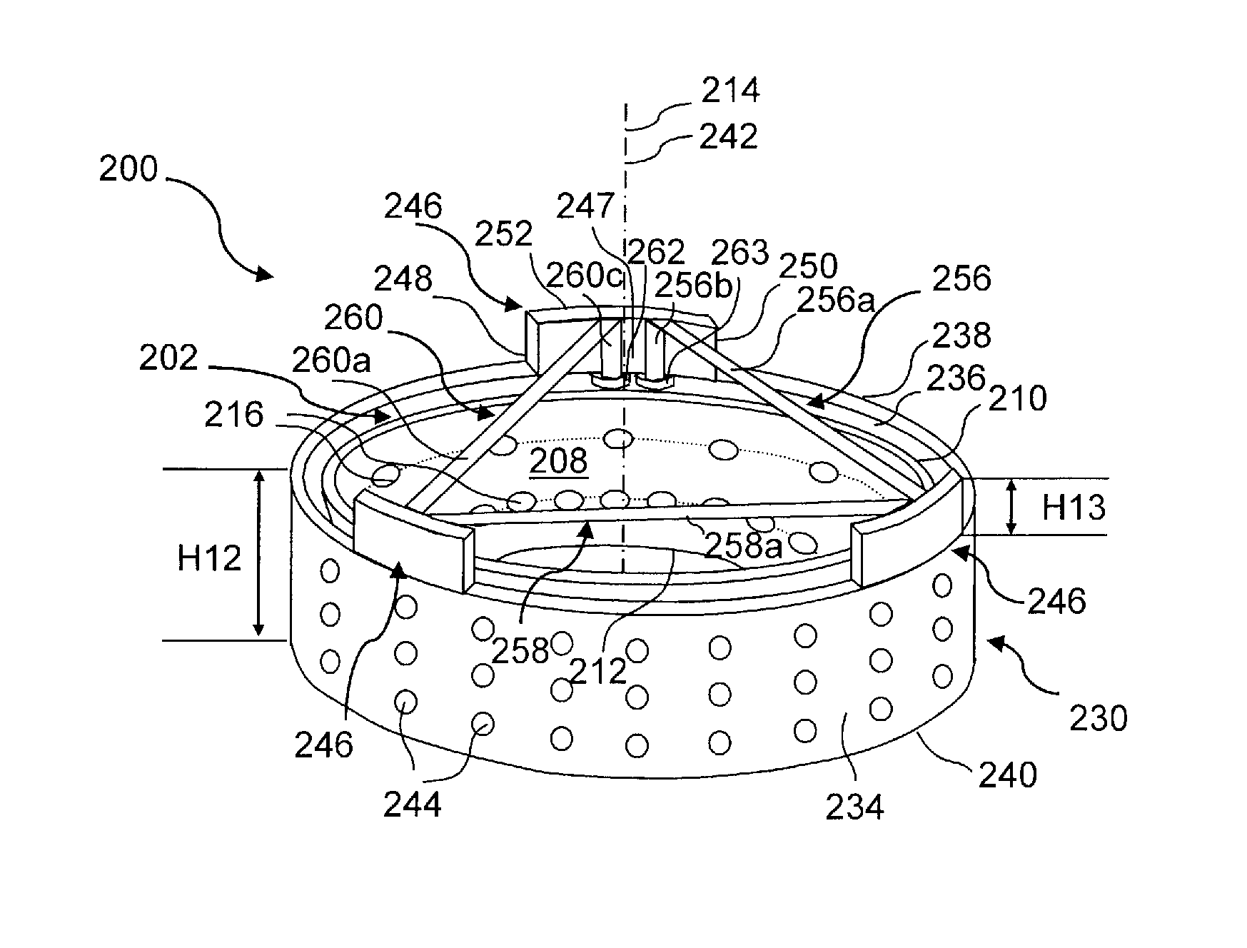
[0099]A removable flame heat transfer regulating apparatus was made of a metal sheet following the illustration which is disclosed for the embodiment 100 of the present invention, comprising an inner circularly arcuate hollow shell 102 and an outer square wall 130. The inner hollow shell 102 was comprised of a top circumference 110 having a diameter of approximately 19.2 cm, a bottom circumference 112 having a diameter of approximately 7.3 cm, and a height of 3 cm between the top and bottom circumferences.

[0100]Two groups of air passages 116 of openings were drilled to penetrate through the inner hollow shell 102 with a diameter of approximately 6 mm for each air passage 116. The air passages 116 in the fir...


PUM


Abstract

The removable apparatus includes an outer wall and improved inner hollow shell which are both positioned on the cooktop of a gas stove to surround an upper section of a burner, where the outer wall surrounds the hollow shell. The improved inner hollow shell is a closed preferably circular hollow member having a larger section connected to a smaller section thereby forming a valley of space to retain dripping liquid substance in cooking. A plurality of openings penetrate through the larger section, wherein more openings are located to its low part. The outer wall has multiple openings which evenly penetrate therethrough. Many extensions projecting upwardly are spaced apart onto a top edge of the outer wall to support a cooking utensil. The apparatus is served as a flame heat transfer regulator for achieving high heating efficiency in cooking and a liquid substance retainer for easily maintaining the cooktop clean.

Description

CROSS-REFERENCE TO RELATED APPLICATIONS[0001]This application is continuation-in-part of U.S. patent application Ser. No. 12 / 658,412 filed on Feb. 10, 2010 which is the divisional application of U.S. Pat. No. 7,708,006 issued on May 4, 2010.BACKGROUND OF THE INVENTION[0002]1. Field of the Invention[0003]The present invention is related to an accessory of a gas stove which is used for increasing heating efficiency of the flame and retaining dripping liquid substance in cooking.[0004]2. Description of the Prior Art[0005]Gas stoves including the cooktops are known. The following 9 United States patents and published patent applications are the closest prior art references related to the present invention.[0006]U.S. Pat. No. 1,156,087 issued to Kupfer on Oct. 12, 1915 for “Flame Shield For Gas Stove” discloses a cylindrical metal tube which is used as a flame shield for a burner of the gas stove. The tube is comprised of a circular wall having an upper end and a lower end, wherein a plu...

Claims


Application Information

Patent Timeline
Patent Type & Authority Applications(United States)
IPC IPC(8): F24C3/08F24C15/10
CPCF24C15/107F24C3/08F24C3/008F24C15/14F24C15/28Y02B40/00
Inventor SUN, YIZHONG
Owner SUN YIZHONG
Why Eureka
Try Eureka