Occluder

a technology of occluder and spondylosis, which is applied in the field of occluder, can solve the problems of destroying the tissue when placing the occluder, affecting the circulation of the affected organ, and affecting the sizing and shaping of the occluder, and achieving the effect of reducing the risk of tissue damag

Active Publication Date: 2020-11-03
CARAG AG
View PDF29 Cites 0 Cited by
  • Summary
  • Abstract
  • Description
  • Claims
  • Application Information

AI Technical Summary

Benefits of technology

[0016]The inventive occluder uses the well-working expanding system of the occluders disclosed in U.S. Pat. No. 6,488,706, US 2003 / 0149463, WO 2005 / 074813 and WO 2012 / 156415. The movement of the elongate members held in two holders can be controlled in any stage of the procedure. The two holders can be moved independently from each other and therefore, the occluder can be recompressed and once again expanded as often as needed. Since a guide wire can be used, the occluder can be exactly introduced at the place to be occluded in a quite easy and efficient way.
[0045]This occluder as well is especially suited for use in LAA. It has also the advantage that its shape and size can be individually chosen by still using the advantages of the guided expansion and recompression of the occluder because of the expanding structure.

Problems solved by technology

The migration of clots from the LAA to the other parts of the body can cause loss of circulation to the affected organ or, when the clots migrate to the brain, it can even cause strokes.
Since LAA is a complex and heterogeneous structure with a rather elliptical ostium, it challenges the sizing and shaping of the occluders.
Since the tissue of the cardiac structure LAA is very thin and fragile, the risk of damaging the tissue when placing the occluder is permanent as well.
In addition, some occluders may be undesirably expelled from the LAA due to forces generated by the heart beat or by atrial fibrillation.
Usually quite big and stable occluders have to be used, which makes delivering of the implant to the LAA more difficult.
In addition, these occluders have to remain within the LAA passage, even when they are already overgrown.

Method used


Image

  • Occluder
  • Occluder
  • Occluder

Examples


first embodiment

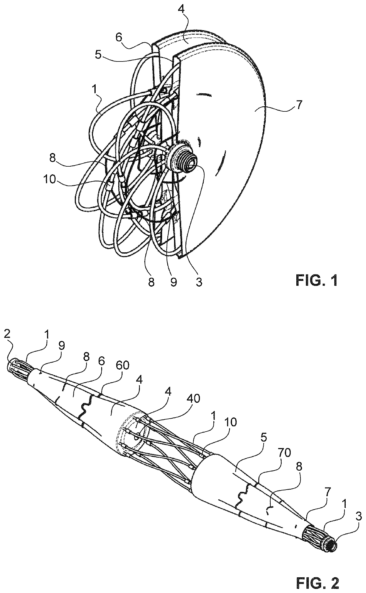
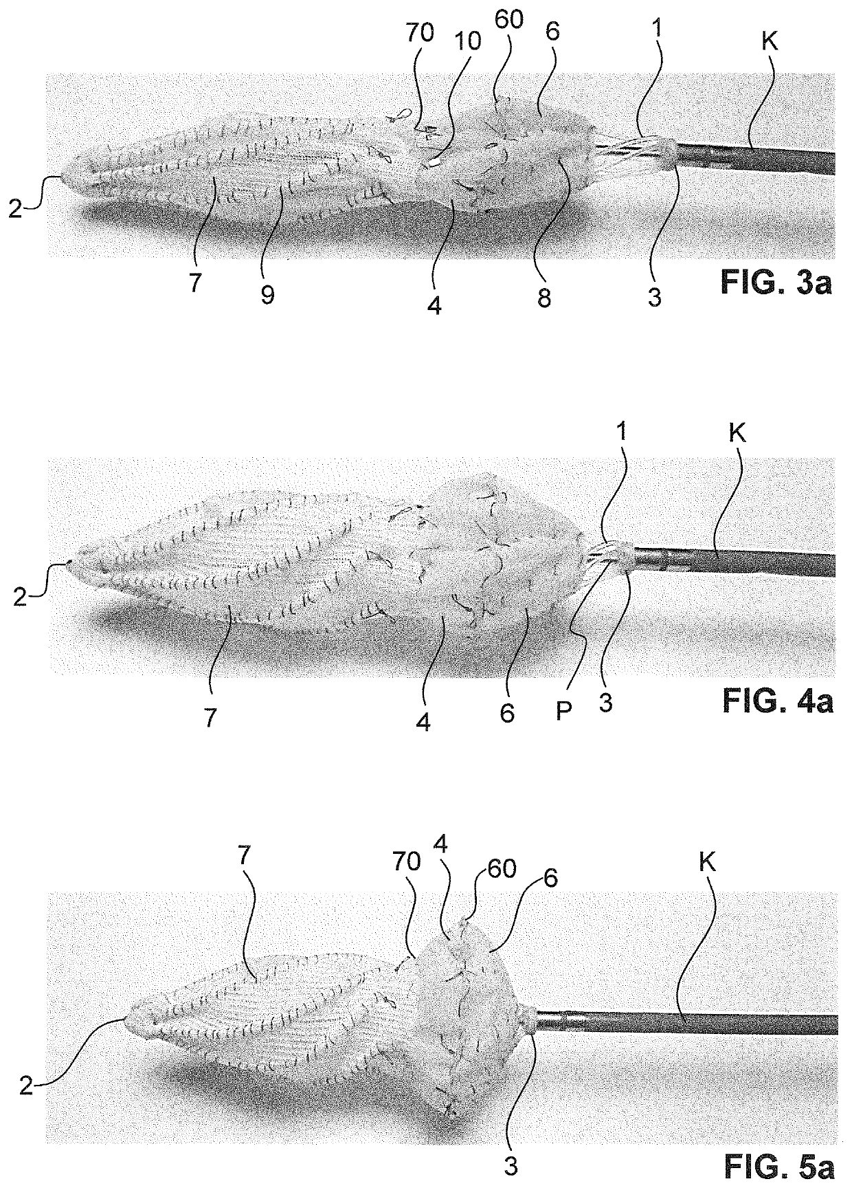
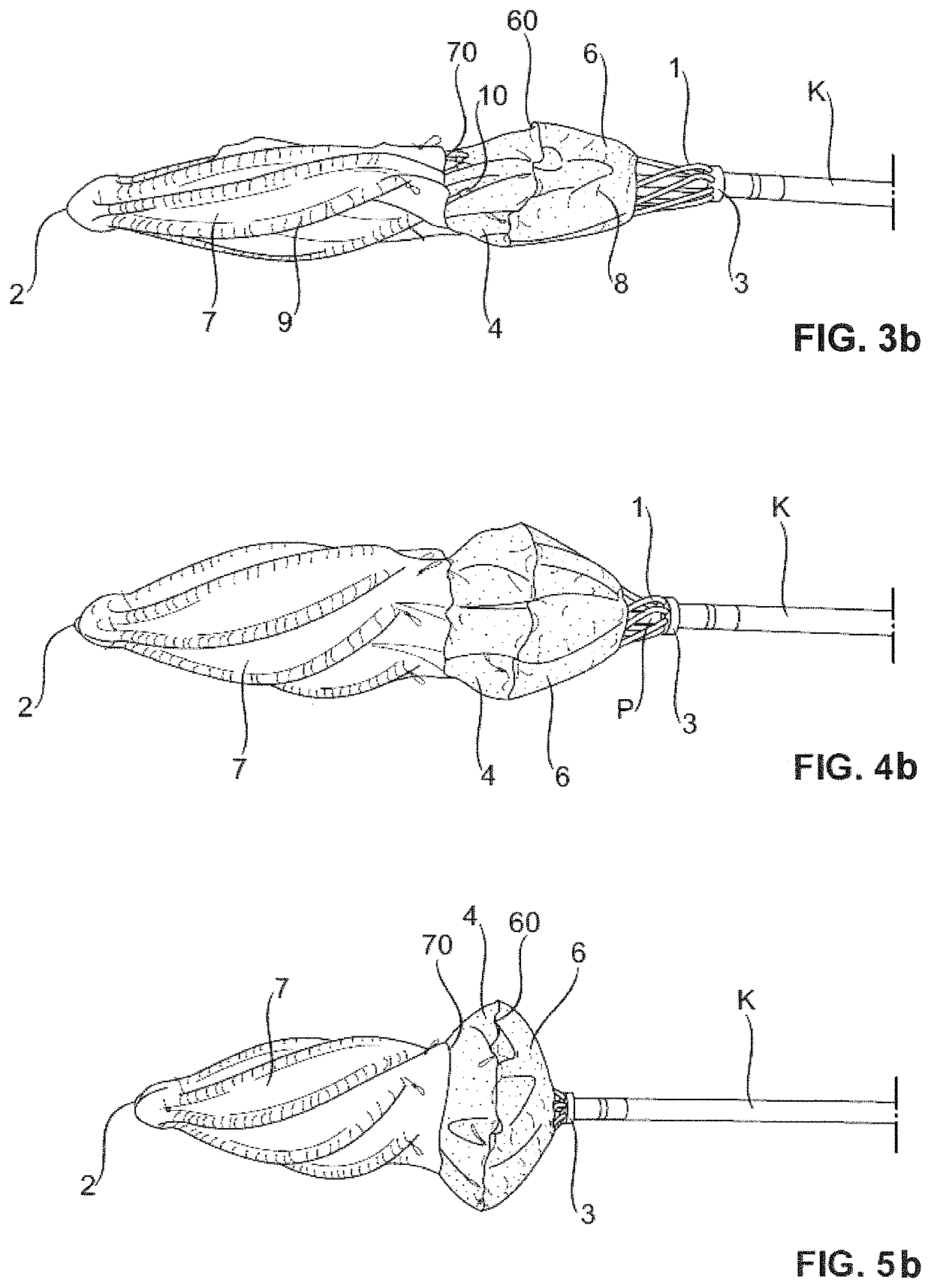
[0092]FIGS. 3 to 7 show an inventive occluder especially capable to be used for closing a left atrial appendage (LAA). The expanding structure is the same as described above. It comprises a multiple of thin elongate members 1, wherein each elongate member 1 is attached or held with one end in the first holder 2 and with the other end in the second holder 3. Preferably, the occluder comprises 3 to 10 elongate members 1, most preferably 8 elongate members.

[0093]The first holder 2 is a distal holder, the second holder 3 is a proximal holder. Preferably, both holders 2, 3 include markers for X-ray guidance. For example, the first holder 2 includes a Phynox-nut and the second holder 3 includes a PtIr-marker. The elongate members 1 are preferably made of resorbable PLGA filaments.

[0094]The occluder further comprises the first membrane 4 and the first cover or jacket 6 as described above, wherein the first membrane 4 and the first jacket 6 are here, contrary to FIGS. 1 and 2, arranged on t...

fourth embodiment

[0115]FIGS. 14 to 17 show the inventive occluder. No membranes are present at all. The elongate members 1 are enclosed within a first, second and third jacket 6, 7, 6′. The first and third jackets 6, 6′ are made of the same material as mentioned above. They have preferably a disk-shaped basic shape with a central hole for penetration of the control catheter P. They are both attached to the elongate members 1 with threads, wherein each elongate member 1 is sewed separately to the first and third jacket 6, 6′. The second jacket 7 can be made of the same material or another material as the second jacket 7 of the embodiments mentioned above. Preferably it is made of the same material as the first and third jacket 6, 6′. Preferably, each elongate member 1, extending from the first to the second holder 2, 3 as a one single piece is sewed from the first to the second holder 2, 3 along its length with the same or a continuous thread. The stitches are thereby so firm or tight, that the elong...


PUM


Abstract

An occluder for occluding a passage in a body, especially in a left atrial appendage (LAA), comprises elongate members having a first end and a second end, the ends being held in or attached to holders, wherein the elongate members extend independently from each other between the holders and wherein the elongate members are collectively enveloped by at least one jacket. The jacket restricts a bending motion of the elongate members when their first ends are approximated to their second ends by moving the two holders relatively to each other. The occluder uses an expanding structure which can be easily handled whereby the movement of the elongate members is restricted by at the jackets which envelop the elongate members. At least the elongate members can be made of bioresorbable material.

Description

CROSS REFERENCE TO RELATED APPLICATIONS[0001]The present application is a U.S. National Phase Application pursuant to 35 U.S.C. § 371 of International Application No. PCT / EP2015 / 070797 filed Sep. 11, 2015, which claims priority to European Patent Application No. 14184603.0 filed Sep. 12, 2014. The entire disclosure contents of these applications are herewith incorporated by reference into the present application.TECHNICAL FIELD[0002]The present invention relates to an occluder for occluding a passage in a body, especially to a left atrial appendage occluder, and a method to produce such an occluder.PRIOR ART[0003]A variety of devices and techniques have been developed to occlude a vessel or an opening in an organ, such as the heart, of a patient.[0004]U.S. Pat. No. 6,488,706 discloses a well-working implant for occluding a passage in a circulatory system. This implant has its particular application as a cardiological implant by means of which it is possible, for example, to close an...

Claims


Application Information

Patent Timeline
Patent Type & Authority Patents(United States)
IPC IPC(8): A61B17/12A61B17/00
CPCA61B17/12122A61B17/1215A61B17/12145A61B2017/00526A61B2017/00867
Inventor MELLMANN, ANDREASBERNHARD, JÉRÔME
Owner CARAG AG
Why Eureka
Try Eureka