Optoelectronic module and plug arrangement

a technology of optoelectronic modules and plugs, applied in the direction of instruments, optical elements, optical waveguide light guides, etc., can solve the problems of inability to implement appropriate circuitry measures, inability to further accommodate external circuitry in the encapsulation body, and inability to carry out wiring, so as to prevent undesirable heating

Inactive Publication Date: 2006-01-19
INFINEON TECH AG
View PDF18 Cites 26 Cited by
  • Summary
  • Abstract
  • Description
  • Claims
  • Application Information

AI Technical Summary

Benefits of technology

[0008] The present invention is directed to an optoelectronic module which is distinguished by being physically compact. The aim in this case is to prevent undesirable heating caused by electrical circuits. A further aim is to provide a plug arrangement for POF transmission systems, which allows optical fibers to be connected to an optoelectronic module.

Problems solved by technology

These RCLEDs have the disadvantage that they have a resonant-like behavior in the temperature range from about −40° C. to 85° C. In particular, there is a considerable reduction in power at the upper temperature limit.
In the case of transceiver embodiments in which the driver module is encapsulated in the encapsulation body with the RCLED, it is, however, impossible to implement appropriate circuitry measures.
Firstly, it is difficult to additionally accommodate the external circuitry in the encapsulation body and to carry out the wiring.
Secondly, a large amount of heat is developed, because the driver stage and the optical transmission source draw more current at high data rates, and because of the additional external circuitry.
This heating can lead to clouding or blackening of the encapsulation body, and to destruction of the transducer module.
Obviously, this is not satisfactory.

Method used


Image

  • Optoelectronic module and plug arrangement
  • Optoelectronic module and plug arrangement
  • Optoelectronic module and plug arrangement

Examples


Embodiment Construction

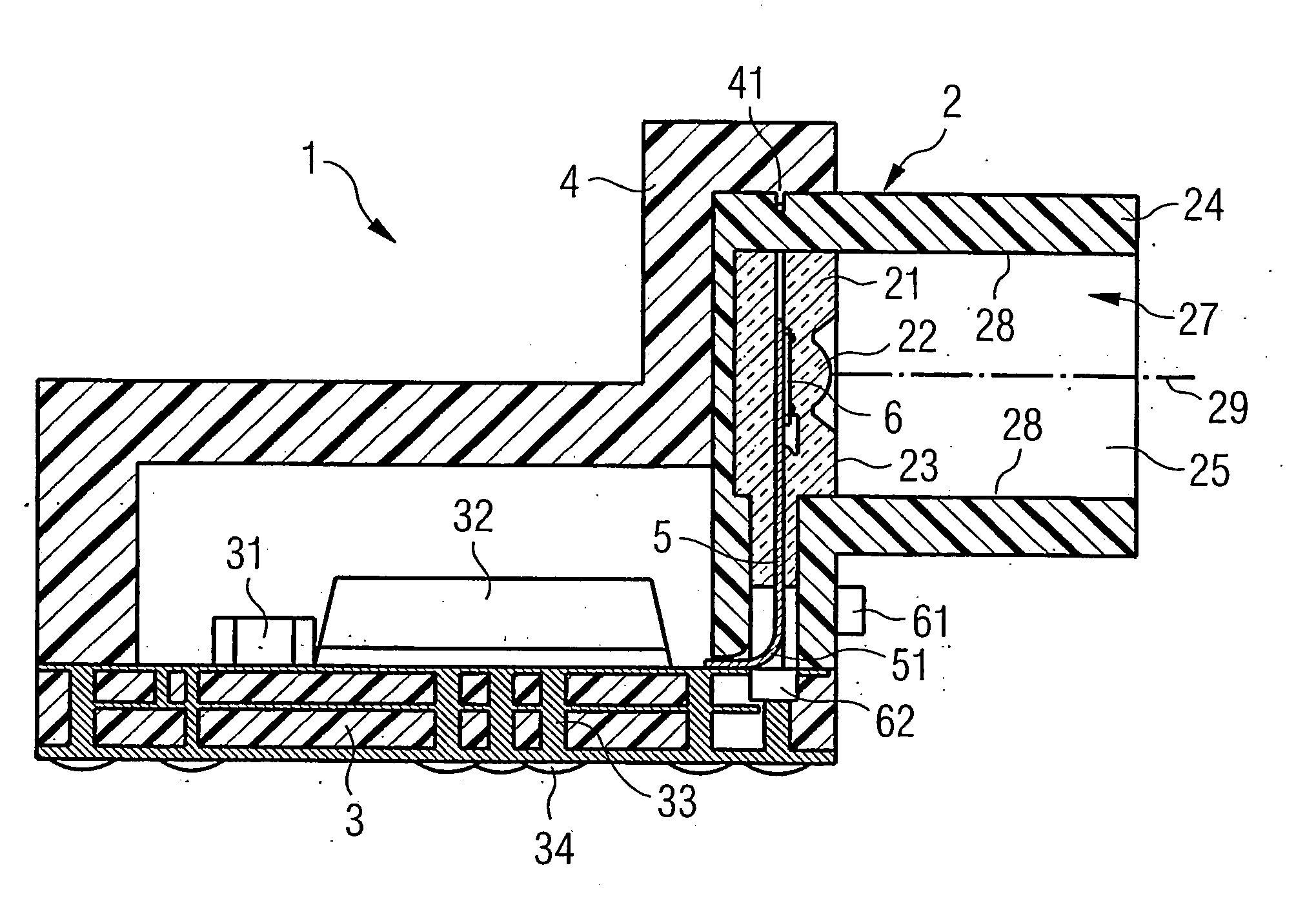
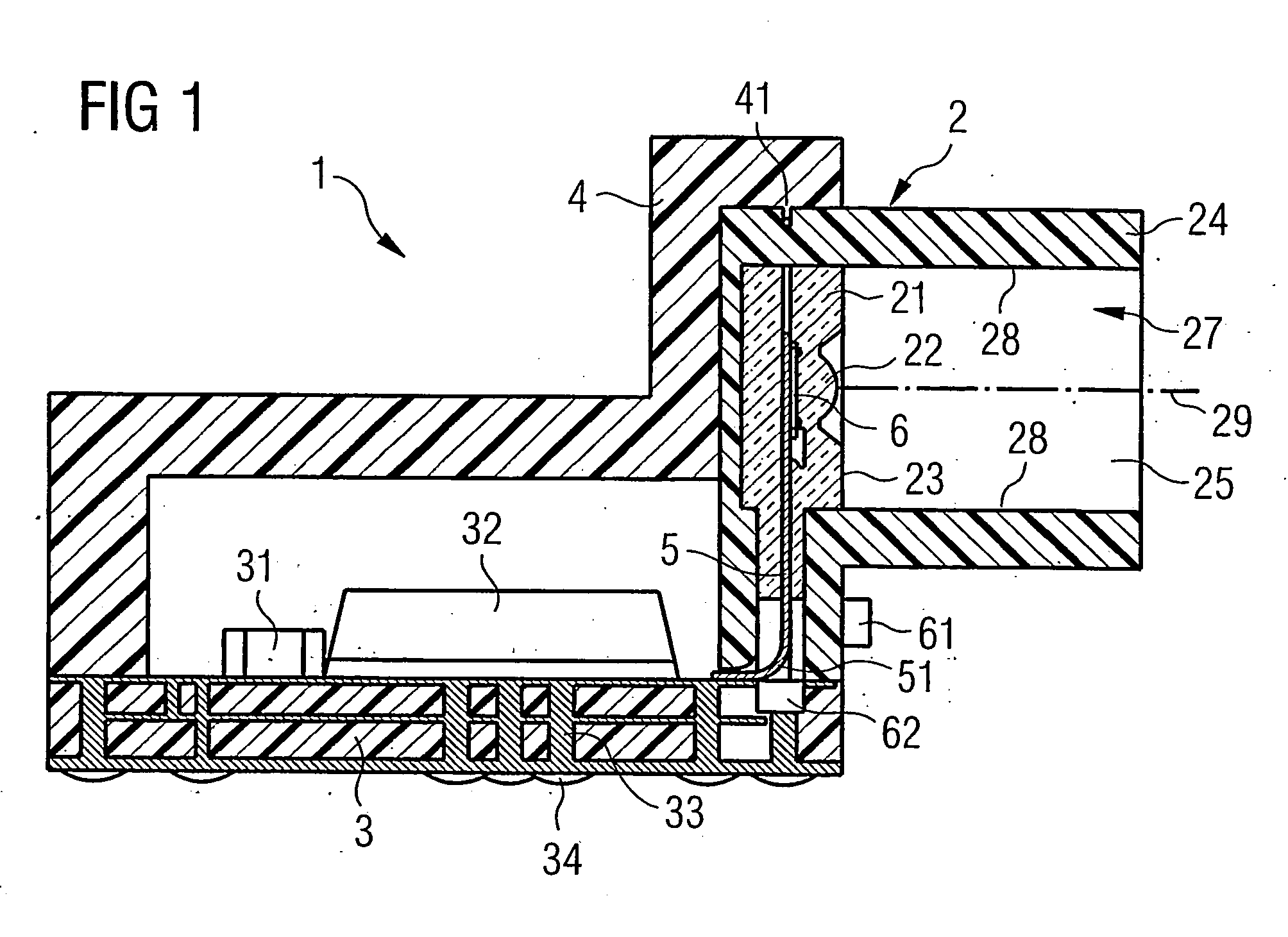
[0050]FIG. 1 shows an optoelectronic module 1 whose main components are a holding and coupling part 2, which is also referred to as a CAI (Cavity AS Interface) housing, and a submount 3 with electrical components. The arrangement of the CAI housing 2 and submount 3 is covered by a housing cover 4. The housing cover is connected to the CAI housing 2 in an interlocking manner via a projection 41.

[0051] The CAI housing 2 is used firstly for holding and for insertion of a mount (lead structure) 5 with a transmitting and / or receiving element, which is in this case an optoelectronic transducer 6, and secondly for forming a coupling area 27 for holding an optical fiber. For this purpose, at one of its ends, the CAI housing has an encapsulation body 21 composed of transparent encapsulation material, which sheaths (secures) the mount 5 together with the optoelectronic transducer 6, which may be in the form of a transmitting element or a receiving element.

[0052] On the one hand, a lens 22 i...


PUM


Abstract

A compact optoelectronic module that prevents undesirable heating by locating the electrical drive and/or receiving (control) circuit outside of the housing containing the optoelectronic transducer. The control circuit is mounted on a submount (PCB). The housing is mounted on the submount adjacent to the control circuit, and the optoelectronic transducer is coupled to the control circuit via a mount (leadframe) that extends substantially perpendicular to the submount plane and is surface mounted on the submount. The housing includes an opening, and a lens is provided between the optoelectronic transducer and the opening and defines an optical axis that is parallel to the submount plane. An encapsulating body is used to secure the optoelectronic transducer and mount inside the housing, and a portion of the encapsulating material is used to form the lens.

Description

FIELD OF THE INVENTION [0001] The invention relates generally to optoelectronic modules, and more particularly to a plug arrangement used in conjunction with an optoelectronic module. One preferred field of application of the invention is low-cost optoelectronic modules which are coupled to POF (Plastic Optical Fiber) optical waveguides. Within this preferred field of application, the invention is particularly suitable for use in multimedia networks, in the in-house area and automotive area. BACKGROUND OF THE INVENTION [0002] DE 199 09 242 A1 discloses an optoelectronic module in which a mount with an optoelectronic transducer is positioned in a module housing and is encapsulated by means of a translucent material which can be shaped. The light is injected or output via an optical fiber, which is coupled to a connecting stub on the module housing. The driver module and the receiving module for the optoelectronic transducer are also located on the mount. [0003] The data rates for POF...

Claims


Application Information

Patent Timeline
Patent Type & Authority Applications(United States)
IPC IPC(8): G02B6/36G02B6/38G02B6/42
CPCG02B6/3893G02B6/4201G02B6/4204G02B6/421G02B6/4246G02B6/4277G02B6/4292H01L2924/3025H01L2224/48091H01L2924/00014H01L2924/00
Inventor SCHUNK, NIKOLAUS
Owner INFINEON TECH AG
Why Eureka
Try Eureka