Contactless power transmission device

a technology of power transmission device and contactless, which is applied in the direction of rail devices, secondary cell servicing/maintenance, transportation and packaging, etc., can solve the problems of impedance mismatch, shorten the time for charging the vehicle battery, and improve the transmission efficiency.

Inactive Publication Date: 2015-01-29
TOYOTA IND CORP
View PDF4 Cites 4 Cited by
  • Summary
  • Abstract
  • Description
  • Claims
  • Application Information

AI Technical Summary

Benefits of technology

[0005]It is an objective of the present disclosure to provide a contactless power transmission device that enables the transmission of the AC power having different magnitudes in a preferable manner and improves the transmission efficiency
[0021]In a preferable manner, the contactless power transmission device further includes a rectifying unit that rectifies the AC power received by the secondary coil to a DC power, the impedance conversion unit is a DC / DC converter that converts the DC power rectified by the rectifying unit by the switching operation. These manners suppress the impedance from the output of the AC power supply to the variable load from being varied between when the first power is transmitted and when the second power is transmitted. This prevents the impedance from being varied due to the transmission of the different powers, thereby suppressing the occurrence of the mismatch in the impedance.

Problems solved by technology

In this case, since the impedance from an output end of the AC power supply to the vehicle battery varies due to the variation in the magnitude of the AC power to be transmitted, a mismatch may occur in the impedance.

Method used


Image

  • Contactless power transmission device
  • Contactless power transmission device
  • Contactless power transmission device

Examples


first embodiment

[0027]Hereinafter, discussion will be made on a first embodiment of a contactless power transmission device or a contactless power transmission system according to the present disclosure.

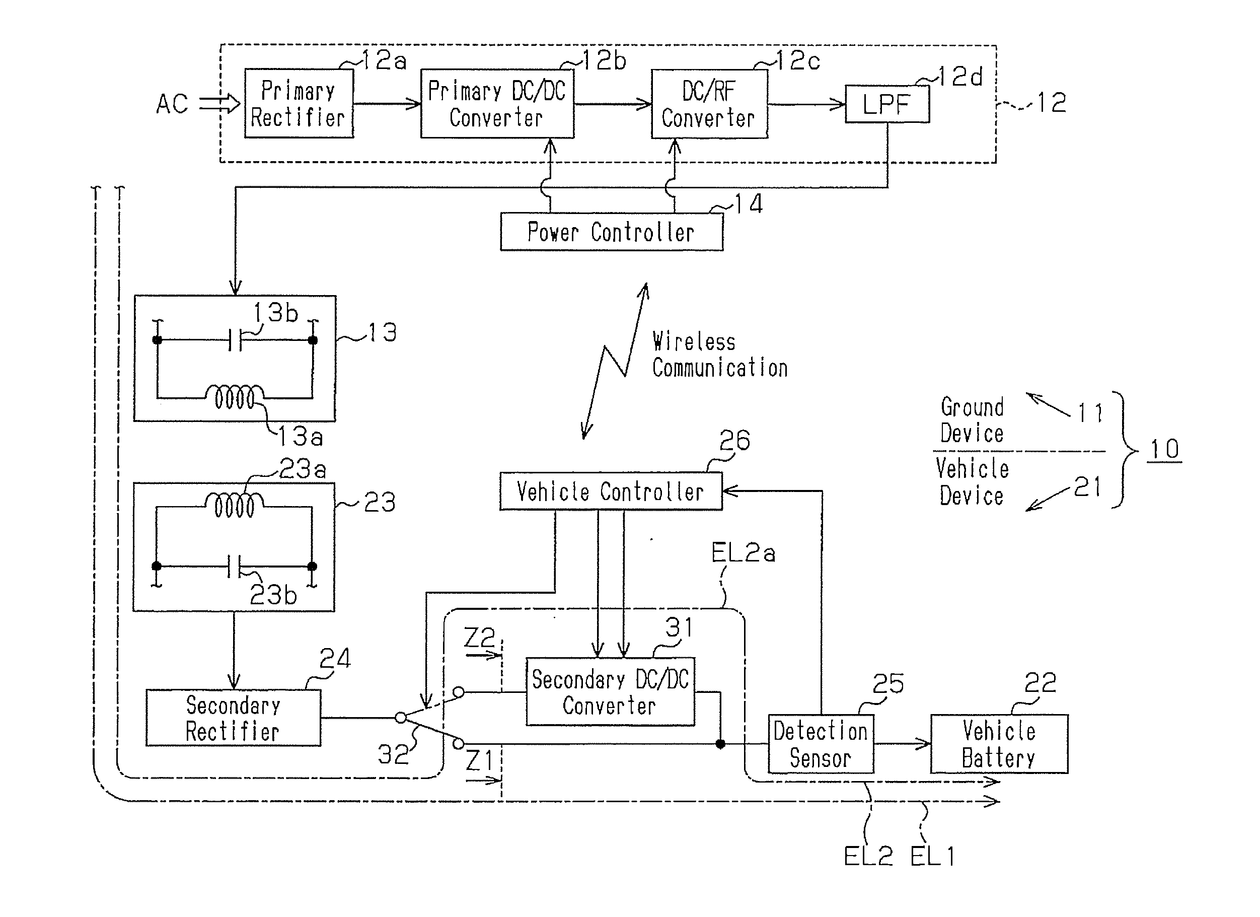
[0028]As shown in FIG. 1, a contactless power transmission device 10 includes a ground device 11 and a vehicle device 21 mounted on a vehicle. The ground device 11 serves as a primary device, namely a power supplying device. The vehicle device 21 serves as a secondary device, namely a power receiving device.

[0029]The ground device 11 includes a high-frequency power supply 12, which is capable of outputting a high-frequency power, namely an AC power, having a certain frequency. The high-frequency power supply 12 is configured to use a system power and output the high-frequency power having a sine wave, and is configured so that an internal resistance is capable of being ignored, namely the internal resistance becomes 0Ω. Specifically, the high-frequency power supply 12 includes a primary rectifier 12...


PUM

PropertyMeasurementUnit
internal resistanceaaaaaaaaaa
resonance frequencyaaaaaaaaaa

Abstract

A contactless power transmission device includes a switching unit that switches a power transmission line so that a first power is transmitted through the first line when an AC power supply outputs a first AC power and so that a second power is transmitted through a second line when the AC power supply outputs a second AC power. An impedance conversion unit is arranged on the second line that converts an impedance from an output of the AC power supply to a variable load when the second power is transmitted through the second line to approach an impedance from the output of the AC power supply to the variable load when the first power is transmitted through the first line.

Description

TECHNICAL FIELD[0001]The present disclosure relates to a contactless power transmission device.BACKGROUND ART[0002]A contactless power transmission device that uses a magnetic field resonance has been known as a common technique for a contactless power transmission device, which does not use a power supply wire, a power transmission cable or the like. For example, a contactless power transmission device described in Japanese Laid-open Patent Publication No. 2009-106136 includes a power supplying device that includes an AC power supply and a primary resonance coil, which receives an AC power from the AC power supply. The contactless power transmission device includes a secondary resonance coil arranged on a vehicle that enables the magnetic field resonance with the primary resonance coil. When the magnetic field resonance occurs between the primary resonance coil and the secondary resonance coil, the AC power is supplied from the power supplying device to the vehicle. The AC power is...

Claims


Application Information

Patent Timeline
Patent Type & Authority Applications(United States)
IPC IPC(8): H02J7/02H01F38/14H02J5/00H02J7/00B60L5/00B60M7/00
CPCH02J7/025H01F38/14H02J5/005B60L5/005B60M7/003H01M10/44Y02T90/14Y02T10/7072B60L53/122B60L53/126H02J2207/20H02J50/12H02J7/00712Y02T10/70Y02E60/10H02J50/80H02J50/10Y02T90/12
Inventor NAKASHIMA, YUTAKAKOIKE, TSUYOSHIKATSUNAGA, HIROSHITAGUCHI, YUICHITOGANO, HIROKIMATSUKURA, KEISUKETSUNEKAWA, YUKIONO, TAKUMA
Owner TOYOTA IND CORP
Why Eureka
Try Eureka