
Ankle strap transformation footwear for slipper and sandal conversion

a technology of ankle straps and footwear, applied in footwear, applications, clothing, etc., can solve the problems of inconvenient storage, lost ankle straps, and lack of ankle straps

Inactive Publication Date: 2015-02-19
PERNIA PATRICK
View PDF0 Cites 11 Cited by
  • Summary
  • Abstract
  • Description
  • Claims
  • Application Information

AI Technical Summary

Benefits of technology

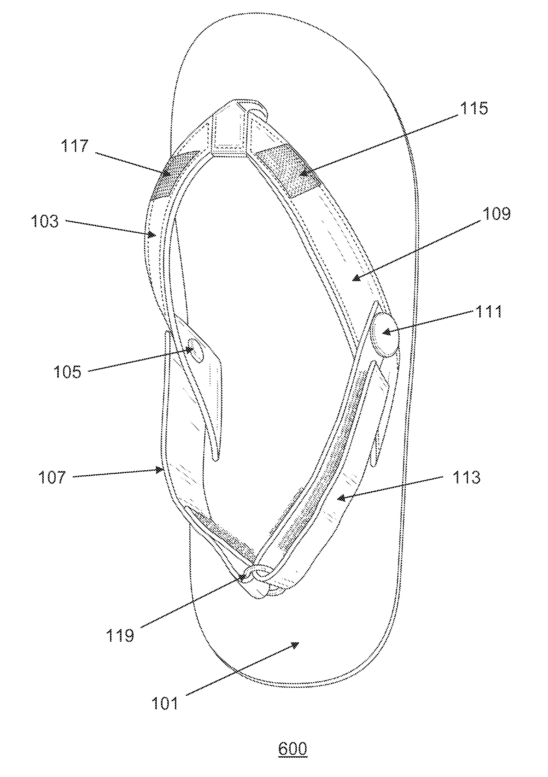
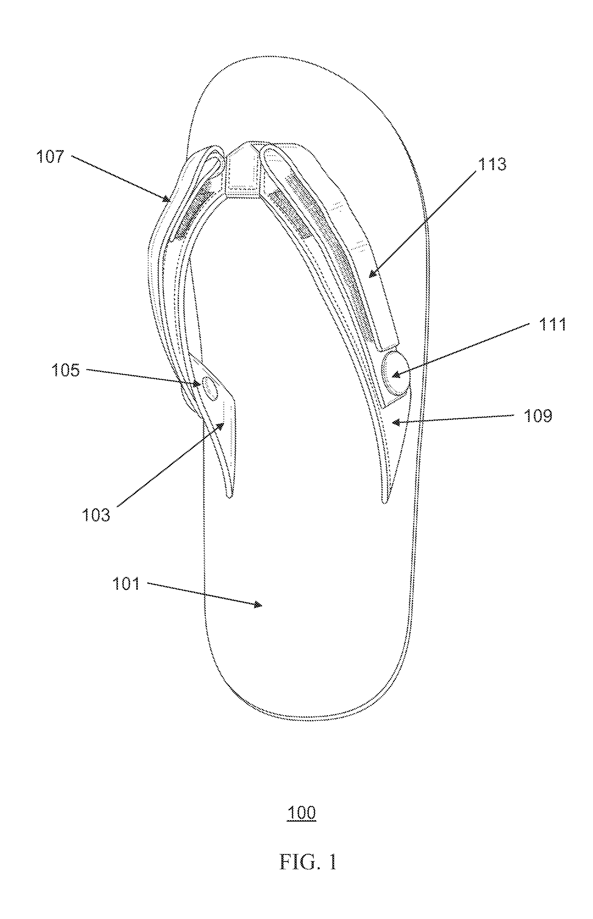
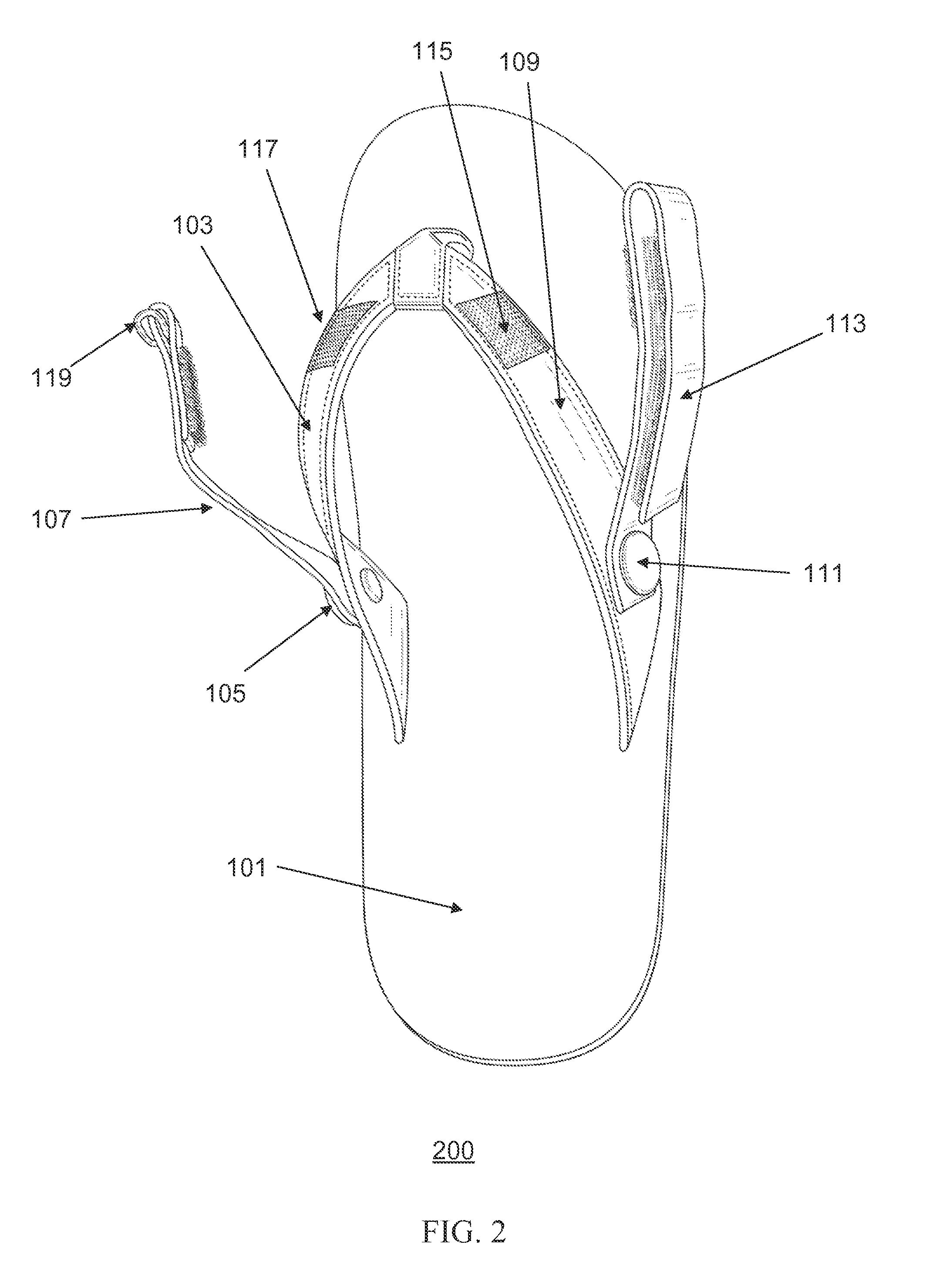
The present invention is about a type of footwear with an ankle strap transformation. The footwear has a cushion to support the foot, a main strap, and two ankle straps. The straps can be folded into a half-shell or a full-shell mode. When in the half-shell mode, the straps can be attached to the main strap or the cushion. When in the full-shell mode, the straps can be interlocked or attached to the main strap and the cushion. This transformation allows the footwear to be used as either an ankle-strapped sandal or an ankle-strapless slipper. The technical effect of this invention is that it provides a versatile and comfortable footwear that can be easily adapted to different situations and activities.

Problems solved by technology

A conventional slipper, on the other hand, can also embody an open toe or closed toe design, but generally lacks an ankle strap because the conventional slipper is not designed for an extended walking.
Although some sandal designs accommodate manual removal of their ankle straps to enable ankle-strapless walking, the manual removal of ankle straps often result in lost ankle straps or inconvenient storage problems, especially if the user is in the middle of walking or away from his or her shoe cabinet.
Furthermore, if the user does not own many different pairs of sandals and slippers, yet keep the convenience and versatility of both categories of footwear without resulting in lost shoe parts, such as removed pieces of ankle straps, conventional sandal and slipper designs may not adequately satisfy the user's preferences and needs.

Method used


Image

  • Ankle strap transformation footwear for slipper and sandal conversion
  • Ankle strap transformation footwear for slipper and sandal conversion
  • Ankle strap transformation footwear for slipper and sandal conversion

Examples


Embodiment Construction

[0015]Specific embodiments of the invention will now be described in detail with reference to the accompanying figures. Like elements in the various figures are denoted by like reference numerals for consistency.

[0016]In the following detailed description of embodiments of the invention, numerous specific details are set forth in order to provide a more thorough understanding of the invention. However, it will be apparent to one of ordinary skill in the art that the invention may be practiced without these specific details. In other instances, well-known features have not been described in detail to avoid unnecessarily complicating the description.

[0017]The detailed description is presented largely in terms of description of shapes, configurations, and / or other symbolic representations that directly or indirectly resemble one or more ankle strap transformation footwear for sandal and slipper conversion. These process descriptions and representations are the means used by those exper...


PUM


Abstract

A novel ankle strap transformation footwear capable of transforming from an ankle-strapped sandal mode to an ankle-strapless slipper mode is disclosed. In the ankle-strapped sandal mode, a first ankle strap piece and a second ankle strap piece are bound together to form a combined ankle strap. In the ankle-strapless slipper mode, the first ankle strap piece and the second ankle strap piece are separated, swiveled forward, and then attached to a main cover or a main strap of the novel ankle strap transformation footwear. Preferably, in the ankle-strapped sandal mode, the first ankle strap piece and the second ankle strap piece utilize attachment strips and a belt loop for binding together. In the ankle-strapless slipper mode, the first ankle strap piece and the second ankle strap piece utilize attachment strips to attach to the main cover or the main strap of the novel ankle strap transformation footwear.

Description

BACKGROUND OF THE INVENTION[0001]The present invention generally relates to footwear. More specifically, the present invention relates to various embodiments of a novel ankle strap transformation footwear for slipper and sandal conversion.[0002]Most sandals and slippers in the market today fall under similar but separate categories of footwear. For example, a conventional sandal typically embodies an “open toe” design, but also sometimes embodies a “closed toe” design with a main cover or a main strap. A sandal that has a main strap separating a big toe from other toes while holding a user's foot is commonly called a “flip-flop” sandal. Furthermore, a sandal typically includes an ankle strap to enable ergonomically-comfortable and extended walking for a user. A conventional slipper, on the other hand, can also embody an open toe or closed toe design, but generally lacks an ankle strap because the conventional slipper is not designed for an extended walking.[0003]Although some sandal...

Claims


Application Information

Patent Timeline
Patent Type & Authority Applications(United States)
IPC IPC(8): A43B3/12A43B3/24
CPCA43B3/126A43B3/122A43B3/242A43B1/0081A43B3/105A43C11/1493
Inventor PERNIA, PATRICK
Owner PERNIA PATRICK
Learn More