Head protection airbag apparatus

a technology for airbags and head protection, which is applied in the direction of pedestrian/occupant safety arrangements, vehicular safety arrangments, vehicle components, etc., can solve the problem of difficult to significantly protrude the inflation portion itself on the front end side of the airbag body toward the inner, and achieve the effect of extending the cloth

Active Publication Date: 2015-03-26
TOYODA GOSEI CO LTD
View PDF13 Cites 16 Cited by
  • Summary
  • Abstract
  • Description
  • Claims
  • Application Information

AI Technical Summary

Benefits of technology

[0032]In accordance with the above-described configuration of the head protection airbag apparatus, at the time of completion of inflation of the airbag body, the end side inflation portion inflates so as to cause the tension cloth arrangement region in which the tension cloth is arranged on the outer peripheral side to be more depressed than other regions which are vertically deviated from the tension cloth arrangement region. Therefore, the tension cloth exhibits an aspect of fitting in the depressed region so that the tension cloth can be suppressed from vertically moving with respect to the end side inflation portion, when the airbag body receives the head of an occupant. As a result, it is possible to protect the head of an occupant more invariably by the end side inflation portion when completely inflated.

Problems solved by technology

In the second head protection airbag apparatus in the related art, since the tension cloth is arranged on the lower end of the airbag body, it is difficult to significantly protrude the inflation portion itself on the front end side of the airbag body toward the inner vehicle side.

Method used


Image

  • Head protection airbag apparatus
  • Head protection airbag apparatus
  • Head protection airbag apparatus

Examples


first embodiment

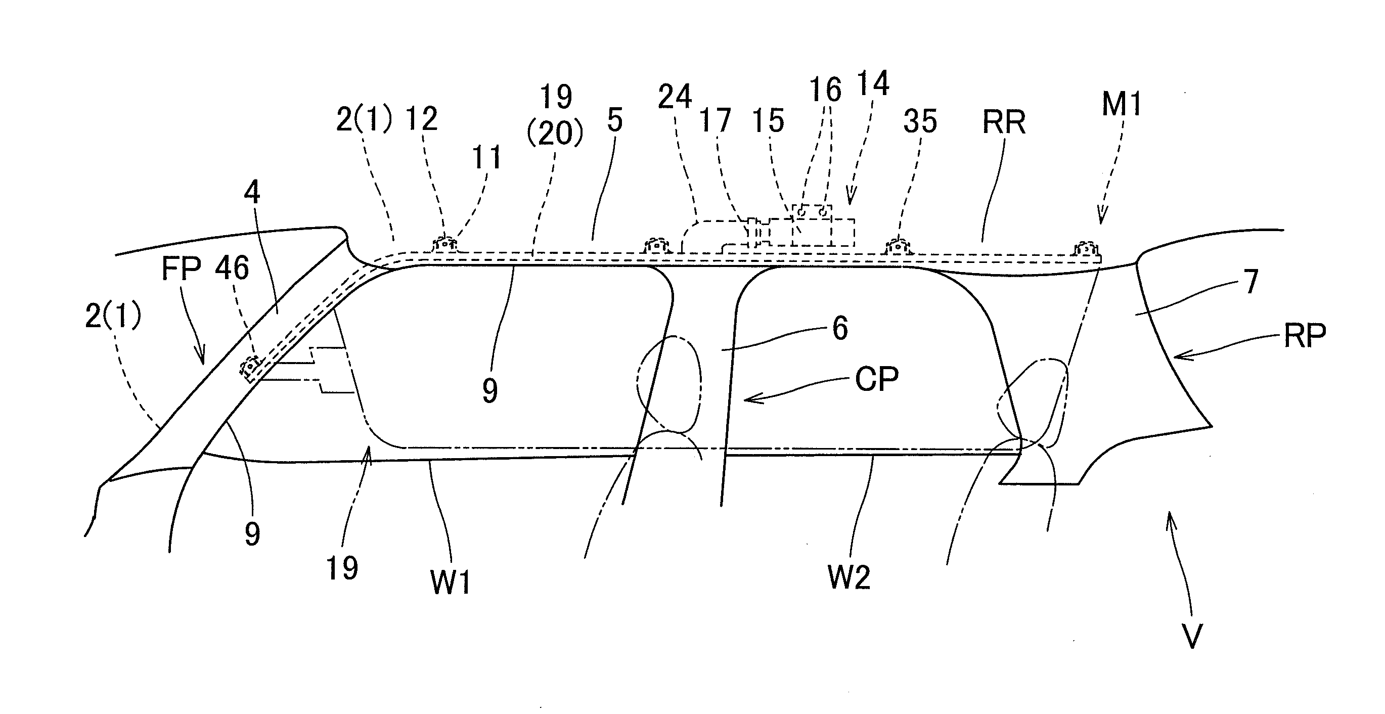
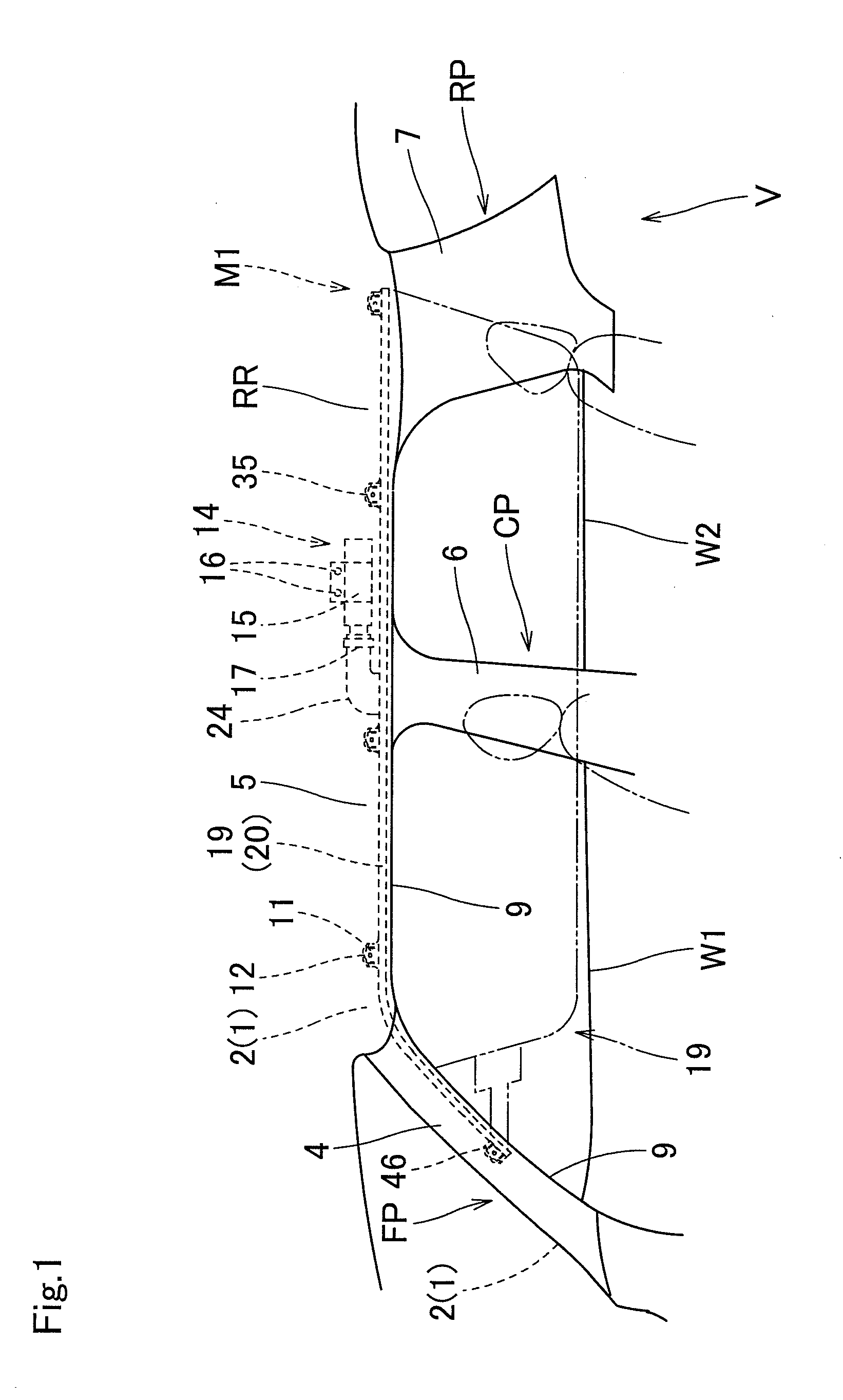
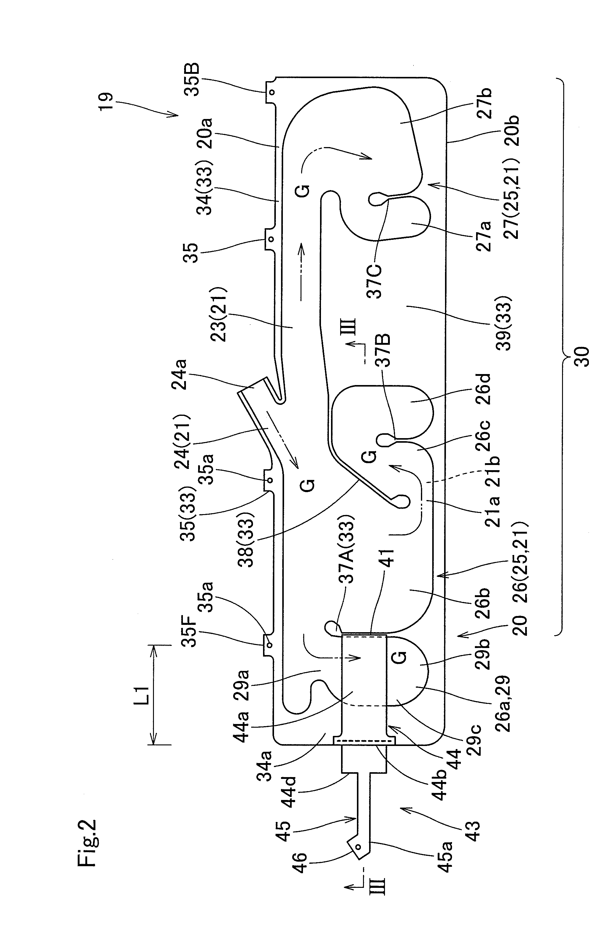
[0071]Subsequently, description will be given regarding the mounting of the head protection airbag apparatus M1 in the first embodiment into the vehicle V. Initially, the airbag 19 is folded. Specifically, the airbag body 20 in a state where the inner vehicle side wall portion 21a and the outer vehicle side wall portion 21b overlap each other to be flatly deployed is folded along with the support portion 44 of the tension cloth 43 so as to cause a lower edge 20b side to approach the upper edge 20a side, thereby contracting the width dimension in the vertical direction. After completing the folding of the airbag 19 in such a manner, a predetermined place for the airbag 19 is wrapped by using a tearable wrapping material for preventing a folding collapse (not illustrated).

[0072]Thereafter, the inflator 14 to which the attachment bracket 15 has attached is connected to the gas inflow port portion 24 of the airbag 19, utilizing the clamp 17. The attachment brackets 11 are fixedly attach...

second embodiment

[0084]As illustrated in FIGS. 10 and 11, the airbag 50 used in the head protection airbag apparatus M2 of the second embodiment includes an airbag body 20A and a tension cloth 43A which is joined to the front end side of the airbag body 20A. The airbag body 20A has the same configuration as the above-described airbag body 20 other than that a front side attachment portion 35FA (end side attachment portion). The front side attachment portion 35FA is arranged on the front side is arranged at a position farther rearward than the slit 41. Therefore, the same reference numerals and signs are applied to the same members, and detailed description thereof will be omitted. In detail, the front side attachment portion 35FA is in an upper portion on the rearward side of the division portion 37A including the slit 41 and is formed so as to be adjacent to the division portion 37A. The tension cloth 43A has the same configuration as the tension cloth 43 of the above-described airbag 19 other than...

third embodiment

[0096]In the head protection airbag apparatus M3 of the third embodiment, thr end side attachment portion 35FD arranged in a region of the end side inflation portion 29 being configured to cause the front edge side of the airbag body 20D to be folded back and being the region to be folded back extends upper than other attachment portions 35. In the end side attachment portion 35FD, the attachment hole 35a formed at the attachment position to the body 1 side is positioned on the upper end side upper than other attachment portions 35. In other words, as illustrated in FIG. 16, the end side attachment portion 35FD is attached onto the body 1 side at a position away to the upper side than other attachment portions 35. Therefore, when folding back a portion on the front edge 29c side in the end side inflation portion 29 so as to be oriented toward the inner vehicle side I, for example, even if the portion is folded back at a portion immediately below the end side attachment portion 35FD,...


PUM


Abstract

In a head protection airbag apparatus, an airbag includes an airbag body and a tension cloth. The airbag body has an end side inflation portion which is arranged in an end portion on the tension cloth side. The end side inflation portion is divided from other general inflation sections in the airbag body by a division portion. The tension cloth is in an arranged state so as to cover an inner vehicle side of the end side inflation portion, allows the base portion side to be joined to an front edge side of the end side inflation portion, is inserted into a slit formed in the division portion while being inverted so as to cover an outer vehicle side of the end side inflation portion, and allows the leading end side to be fixed to the vehicle body side.

Description

CROSS REFERENCE TO RELATED APPLICATIONS[0001]The Present application claims priority from Japanese Patent Applications No. 2013-200438 of Okuhara et al., filed on Sep. 26, 2013, No. 2014-106495 of Okuhara et al., filed on May 22, 2014, the disclosure of which is hereby incorporated into the present application by reference.BACKGROUND OF THE INVENTION[0002]1. Field of the Invention[0003]The present invention relates to a head protection airbag apparatus having a configuration including an airbag which is configured to be folded and accommodated on an upper edge side of a window on an inner vehicle side, of which the upper edge side is fixedly attached onto a vehicle body side, and which allows inflation gas to flow in from an inflator to deploy and inflate so as to protrude downward and cover the inner vehicle side of the window. The present invention particularly relates to a head protection airbag apparatus which is suitable for use at the time of a diagonal collision in which an i...

Claims


Application Information

Patent Timeline
Patent Type & Authority Applications(United States)
IPC IPC(8): B60R21/2338B60R21/232
CPCB60R21/2338B60R21/232B60R2021/23386B60R2021/0048B60R2021/0009
Inventor OKUHARA, MASAAKIKAWAMURA, KOJIHASHIDO, TATSUYA
Owner TOYODA GOSEI CO LTD
Why Eureka
Try Eureka