Catheter for removing foreign body in blood vessel

a blood vessel and foreign body technology, applied in the field of blood vessel foreign body removal catheters, can solve the problems of difficult to capture all, thrombosis is clogged in the catheter, peripheral vascular occlusion, etc., and achieve the effect of effectively nodulizing, avoiding damage to the guide unit, and effectively sucking and removing

Inactive Publication Date: 2015-06-04
KAWASUMI LABORITORIES INC +1
View PDF15 Cites 19 Cited by
  • Summary
  • Abstract
  • Description
  • Claims
  • Application Information

AI Technical Summary

Benefits of technology

[0034]According to the catheter for removing foreign body in blood vessel of the present invention as described in (1), because the capturing chamber has an opening area decreased as it goes from a distal end opening of the capturing chamber toward a proximal end opening of the capturing chamber and also, in the expanded state of the capturing unit, the cutting unit is arranged more toward the proximal end opening of the capturing chamber than the distal end opening of the capturing chamber, a foreign substance, such as thrombus, can be guided from the distal end opening having a large opening area in the capturing chamber toward the proximal end opening having a small opening area, and thus can be effectively condensed in the proximal end opening. Also, by cutting the foreign substance, which has been condensed in the proximal end opening of the capturing chamber, by the cutting unit, the foreign substance can be effectively nodulized. Therefore, a large foreign substance, which would not be previously sucked into a catheter, can be also nodulized to be effectively sucked and removed. In addition, because the cutting unit is arranged more toward the proximal end opening of the capturing chamber than the distal end opening of the capturing chamber, the cutting unit is not exposed in a blood vessel upon cutting, thereby ensuring safety.
[0035]According to the catheter for removing foreign body in blood vessel of the present invention as described in (2), because the power transmitting member is another tube having a lumen, through which a guide wire can be inserted, the catheter can be directed by the guide wire to be reliably guided to a site, where the foreign substance is generated.
[0036]According to the catheter for removing foreign body in blood vessel of the present invention as described in (3), because the power transmitting member is another tube having a lumen, through which a guide unit for guiding a foreign substance into the capturing chamber can be inserted, the foreign substance can be effectively guided and condensed into the capturing chamber by the guide unit.
[0037]According to the catheter for removing foreign body in blood vessel of the present invention as described in (4), because a radiographic marker is provided to allow a distance between the guide unit and the cutting unit to be seen by eyes, contact between the cutting unit and a balloon can be prevented, thereby avoiding damage of the guide unit by the cutting unit.
[0038]According to the catheter for removing foreign body in blood vessel of the present invention as described in (5), because the cutting unit is a foldable propeller-shaped member, even a large foreign substance can be sucked and removed by reliably cutting and nodulizing the foreign substance by the propeller-shaped member.
[0039]According to the catheter for removing foreign body in blood vessel of the present invention as described in (6), because unevenness is formed on an inner surface of the capturing chamber along a circumferential direction thereof, the foreign substance can be ground and crushed by the unevenness formed on the inner surface of the capturing chamber and the propeller-shaped member, thereby effectively nodulizing the foreign substance.

Problems solved by technology

Even in the case of the catheter having such a foreign substance removing filter, it is difficult to capture all fragments of atheromatous plaque or thrombus peeled from a blood vessel wall, and in addition, there are problems in that in a case of a large thrombus or the like, the thrombus is clogged in the catheter or does not enter the catheter, or the like.
If such thrombus, which cannot be recovered and is freed, enters a peripheral vascular, there is a risk of causing peripheral vascular occlusion or the like.

Method used


Image

  • Catheter for removing foreign body in blood vessel
  • Catheter for removing foreign body in blood vessel
  • Catheter for removing foreign body in blood vessel

Examples


first embodiment

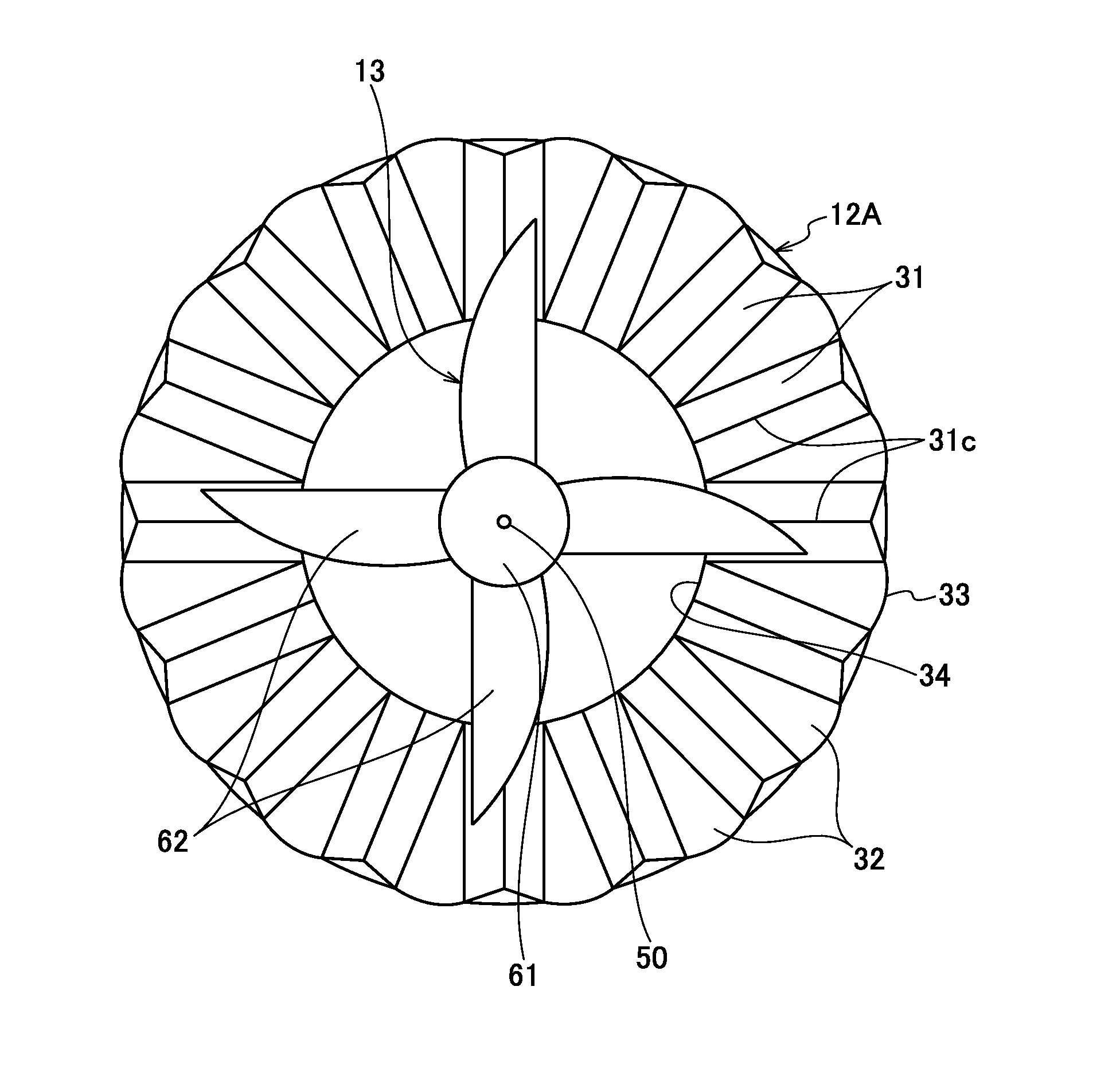
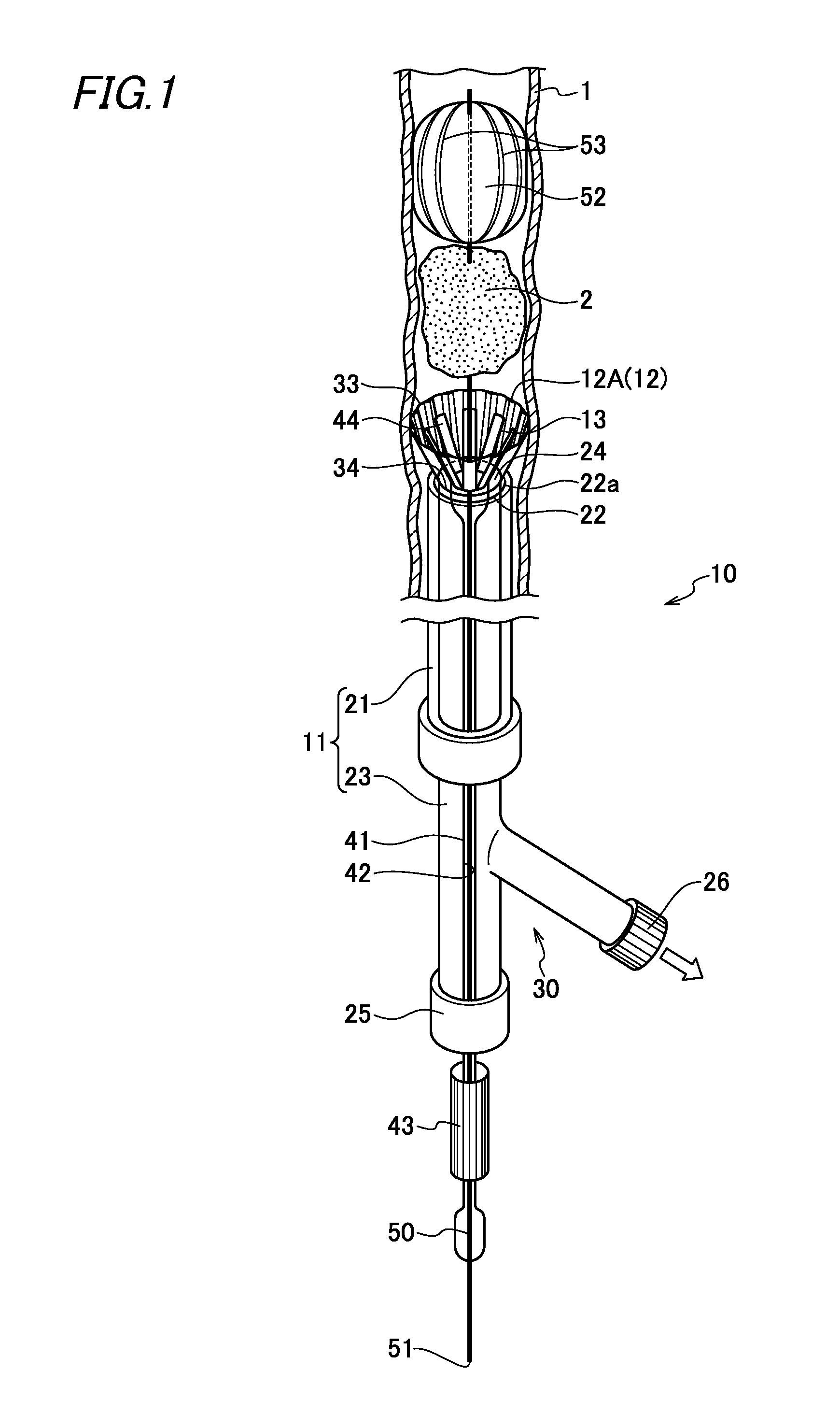
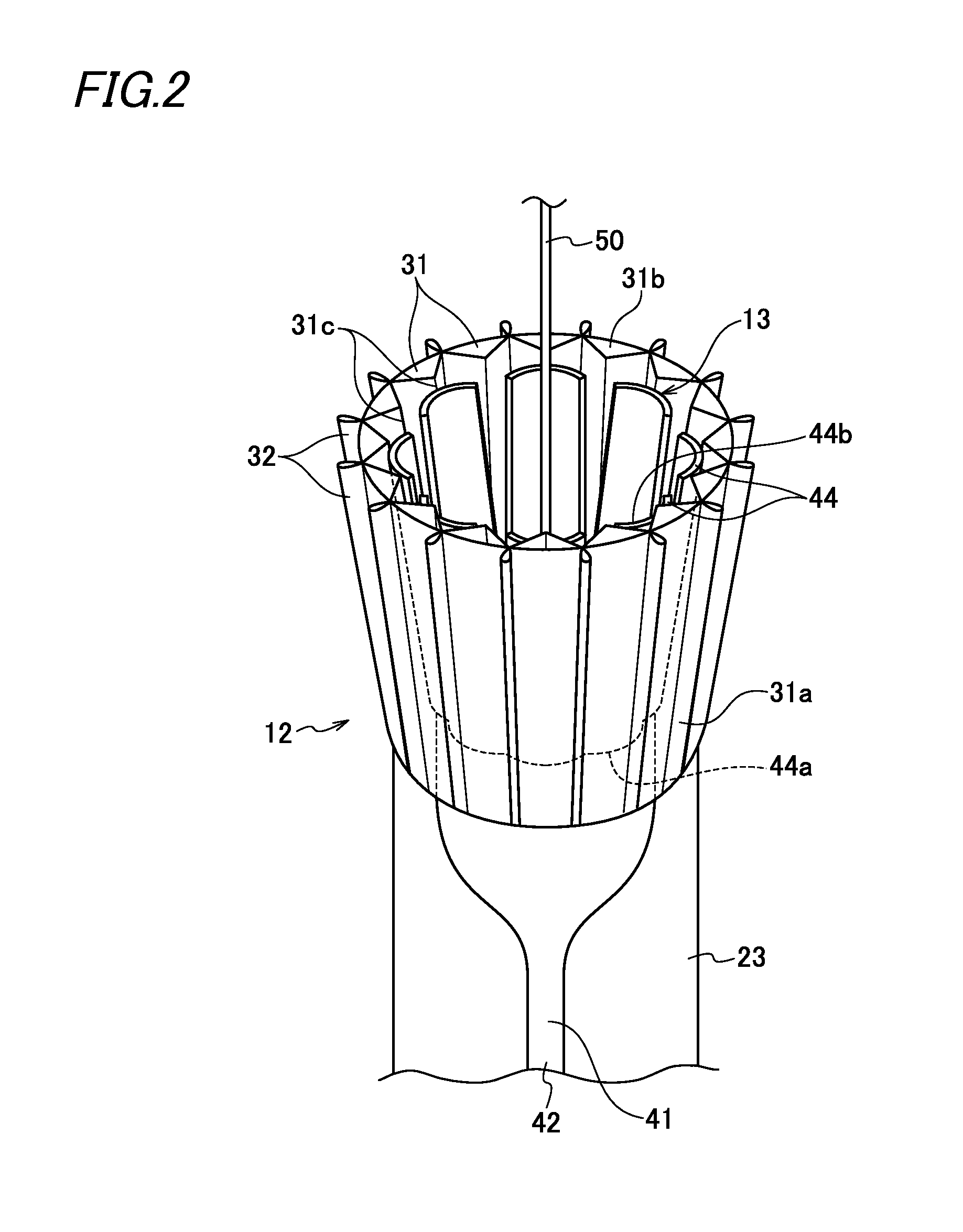
[0051]FIG. 1 is a configuration view of a catheter for removing foreign body in blood vessel according to a first embodiment of the present invention. As shown in FIG. 1, the catheter for removing foreign body in blood vessel 10 has a sheath 11, a capturing unit 12 and a cutting unit 13.

[0052]The sheath 11 includes a first tube 21 having a first lumen 22 and a second tube 23 having a second lumen 24 and has a double lumen structure in which the second tube 23 is inserted through the first lumen 22 of the first tube 21 and thus is adapted to be movable in first lumen 22 in an axial direction of the first tube 21.

[0053]The first and second tubes 21 and 23 are molded of an elastically deformable material, such as polyethylene, polyethylene terephthalate, polypropylene, polyurethane, polyamide elastomer, polyimide, polyimide elastomer, copolymers thereof, silicone rubber, or natural rubber, and have a substantially uniform outer diameter over a longitudinal direction thereof. Also, the ...

second embodiment

[0091]Next, a second embodiment of a catheter for removing foreign body in blood vessel will be described with reference to FIGS. 5 and 6. Meanwhile, in an catheter for removing foreign body in blood vessel according to each of the following embodiments, a cutting unit is only different from that in the catheter for removing foreign body in blood vessel according to the first embodiment and the other portions are identical to those in the catheter for removing foreign body in blood vessel according to the first embodiment of the present invention, and accordingly, the cutting unit will be only illustrated and described.

[0092]FIG. 5A is a perspective view of a cutting unit, which is in a contracted state, according to the second embodiment, FIG. 5B is a perspective view of the cutting unit, which is in an expanded state, and FIG. 6 is an enlarged top view of a capturing unit and the cutting unit, which are in an expanded state, according to the second embodiment.

[0093]As shown in FIG...

third embodiment

[0098]Next, a third embodiment of a catheter for removing foreign body in blood vessel according to the present invention will be described with reference to FIGS. 7 and 8.

[0099]As shown in FIGS. 7 and 8, the cutting unit 13 of the present embodiment is formed of a meshed member 65. The meshed member 65 is constituted of a plurality of wire materials 66 fixed on a distal end of a third tube 41 and extending in an axial direction and ring-shaped wire materials 67 coupled to the plurality of wire materials 66 at predetermined intervals. Meanwhile, lengths of the ring-shaped wire materials 67 are set to have the shortest length in ring-shaped wire materials 67 arranged on end sides of the wire materials 66 and to be gradually lengthened as they go toward the middle part in an axial direction of the wire materials 66.

[0100]The wire materials 66 are formed of a shape memory alloy, which is shape-memorized to have a generally elliptical shape in a natural state, and are deformable into an...


PUM


Abstract

A capturing unit provided on a distal end of a second tube can be deformed into a contracted state and an expanded state, in which the capturing unit is deployed to form a capturing chamber. The capturing chamber has an opening area decreased as it goes from a distal end opening of the capturing chamber toward a proximal end opening of the capturing chamber. A third tube rotatable relative to the second tube and a cutting unit provided on a distal end of the third tube for cutting a foreign substance are arranged in a second lumen. In the expanded state of the capturing unit, the cutting unit is arranged more toward the proximal end opening of the capturing chamber than the distal end opening.

Description

CROSS-REFERENCE TO RELATED APPLICATION[0001]This application is based upon and claims the benefit of priority from U.S. Provisional Patent Application No. 61 / 911,022 filed on Dec. 3, 2013; the entire contents of which are incorporated herein by reference.TECHNICAL FIELD [0002]The present invention relates to a catheter for removing foreign body in blood vessel, and more particularly, to a catheter for removing foreign body in blood vessel, which captures / crushes a foreign substance, such as thrombus, which embolizes a blood vessel and is adhered on a blood vessel wall, and thus allows the foreign substance to be effectively sucked and removed through the catheter to the outside of the body.BACKGROUND ART[0003]To reperfuse a blood vessel, in which stenosis or occlusion is caused due to atheromatous plaque or thrombus, an occlusion substance within the blood vessel has to be removed. A balloon catheter in which a foreign substance removing filter, such a annular wire or a mesh is stor...

Claims


Application Information

Patent Timeline
Patent Type & Authority Applications(United States)
IPC IPC(8): A61B17/3207A61B17/221
CPCA61B17/320758A61B17/320725A61B17/32075A61B2017/2212A61B2017/320766A61B2017/320775A61B2017/22001A61B17/221A61B2017/22072A61B2017/22078A61B2017/22079A61B2017/2215A61B2017/320716A61B2017/320733A61B2217/005
Inventor YAMANOUCHI, DAI
Owner KAWASUMI LABORITORIES INC
Why Eureka
Try Eureka