
Frequency-sensitive shock absorber
a frequency-sensitive and shock-absorbing technology, applied in the direction of shock-absorbing devices, vibration dampers, springs/dampers, etc., can solve the problems of difficult to satisfy both ride comfort and steering stability, and achieve the effect of reducing the cos
- Summary
- Abstract
- Description
- Claims
- Application Information
AI Technical Summary
Benefits of technology
Problems solved by technology
Method used
Image

Examples
Embodiment Construction
[0020]Hereinafter, a frequency-sensitive shock absorber according to a preferred embodiment of the present invention will be described in detail with reference to the accompanying drawings.
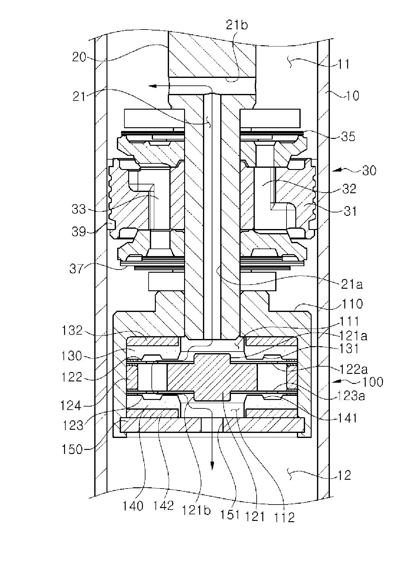
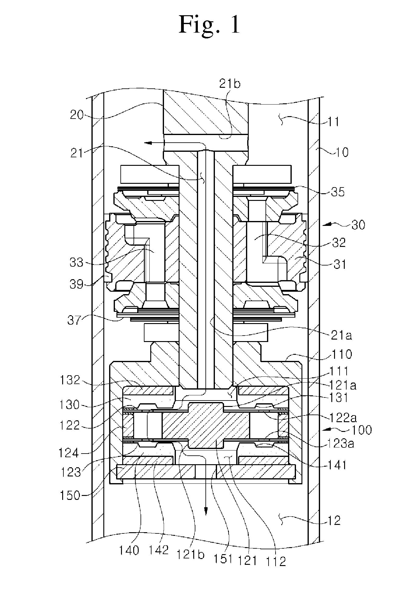
[0021]As illustrated in FIG. 1, a frequency-sensitive shock absorber includes a cylinder 10 and a piston rod 20. The cylinder 10 has a substantially cylindrical shape and is filled with a working fluid such as oil. The piston rod 20 has one end disposed inside the cylinder and the other end extending to the outside of the cylinder.
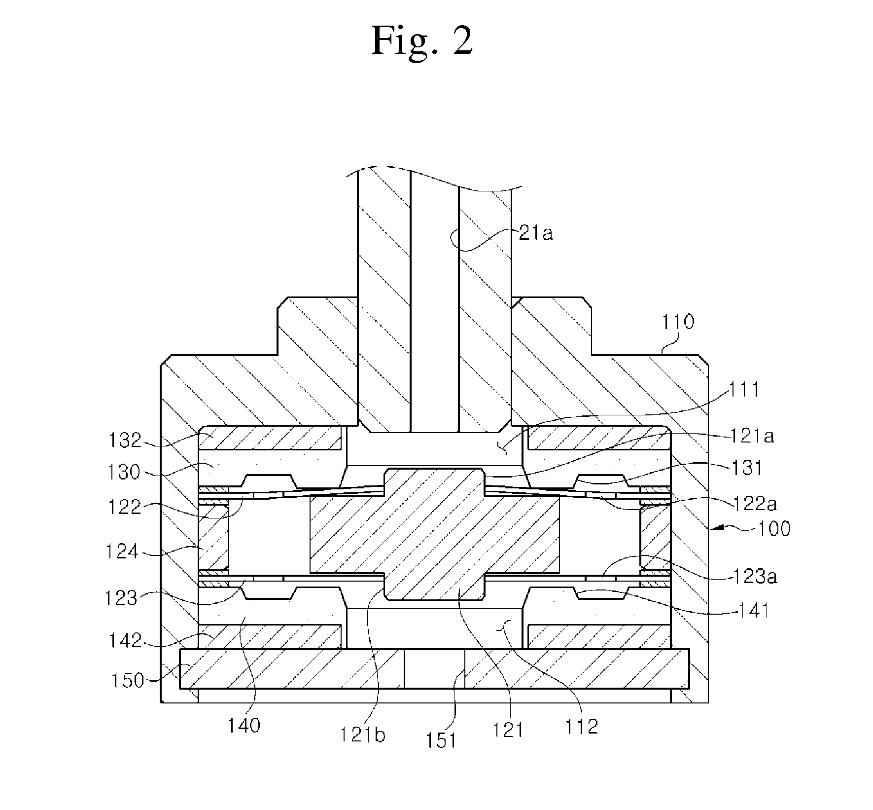
[0022]The valve structure of the shock absorber according to the present invention includes a main piston valve assembly 30 and an auxiliary piston valve assembly 100. The main piston valve assembly 30 is installed at one end of the piston rod 20 and is configured to operate in a state in which the inside of the cylinder 10 is divided into a rebound chamber 11 and a compression chamber 12, and generate a damping force varying according to a moving speed. The auxiliary pi...
PUM
 Abstract
Description
Claims
Application Information