Surface-mount type antenna and antenna apparatus

a technology of antenna apparatus and antenna, which is applied in the direction of resonant antennas, substantially flat resonant elements, elongated active element feed, etc., can solve the problems of difficult resonant frequency adjustment operation, inability to readily achieve the desired antenna characteristics as designed with stability, etc., to achieve satisfactory antenna characteristics with stability, enhance radiation efficiency, and reduce cost

Inactive Publication Date: 2006-04-11
KYOCERA CORP
View PDF14 Cites 20 Cited by
  • Summary
  • Abstract
  • Description
  • Claims
  • Application Information

AI Technical Summary

Benefits of technology

[0014]The invention has been devised in view of the above-described problems with the conventional art, and accordingly its object is to provide a surface-mount type antenna and an antenna apparatus that succeed in readily attaining satisfactory antenna characteristics with stability, in enhancing radiation efficiency, and in achieving miniaturization and cost reduction.

Problems solved by technology

In this case, however, the variation of the resonant frequency corresponding to the cut length is so significant that the resonant-frequency adjustment operation becomes difficult.
As a result, the desired antenna characteristics as designed cannot be readily attained with stability.

Method used


Image

  • Surface-mount type antenna and antenna apparatus
  • Surface-mount type antenna and antenna apparatus
  • Surface-mount type antenna and antenna apparatus

Examples


first embodiment

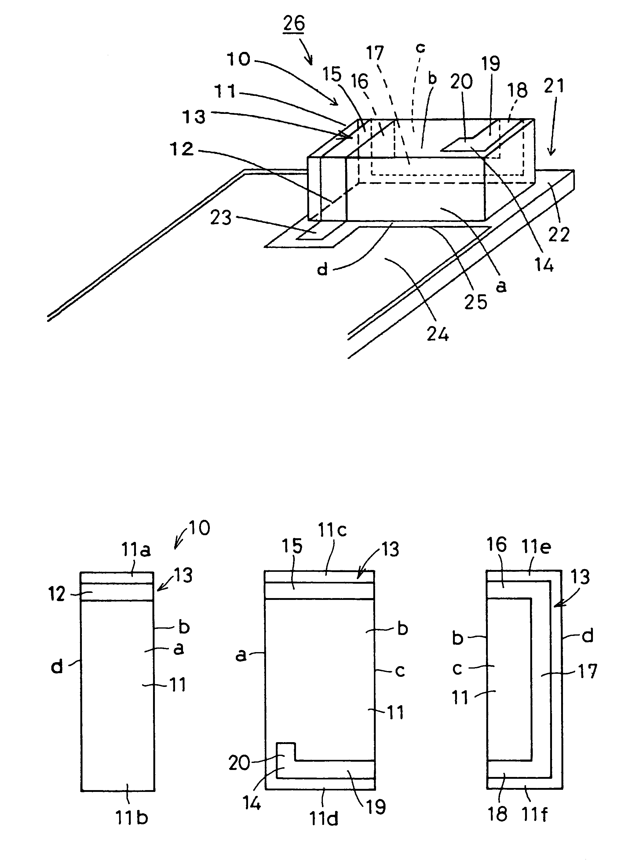
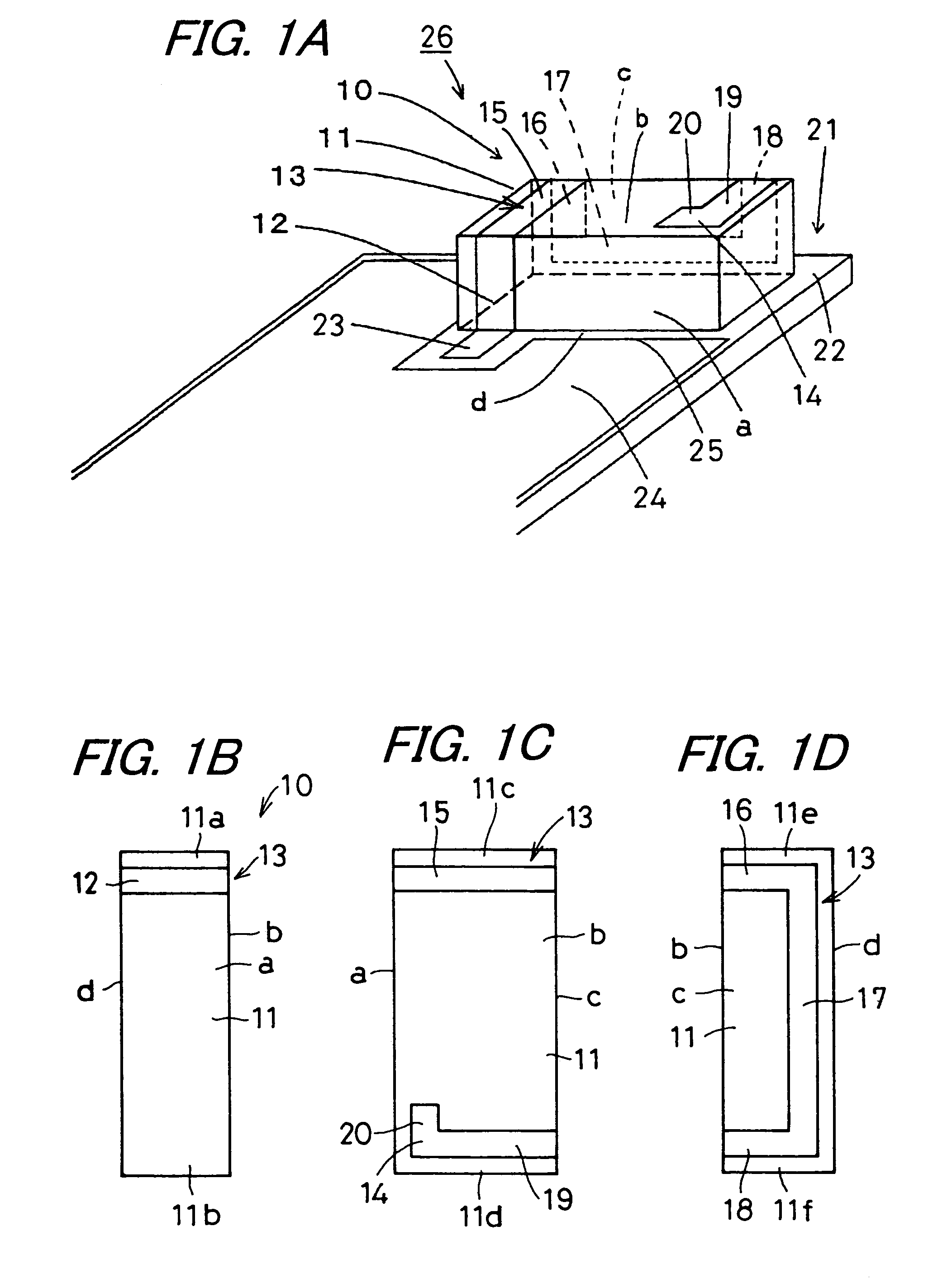
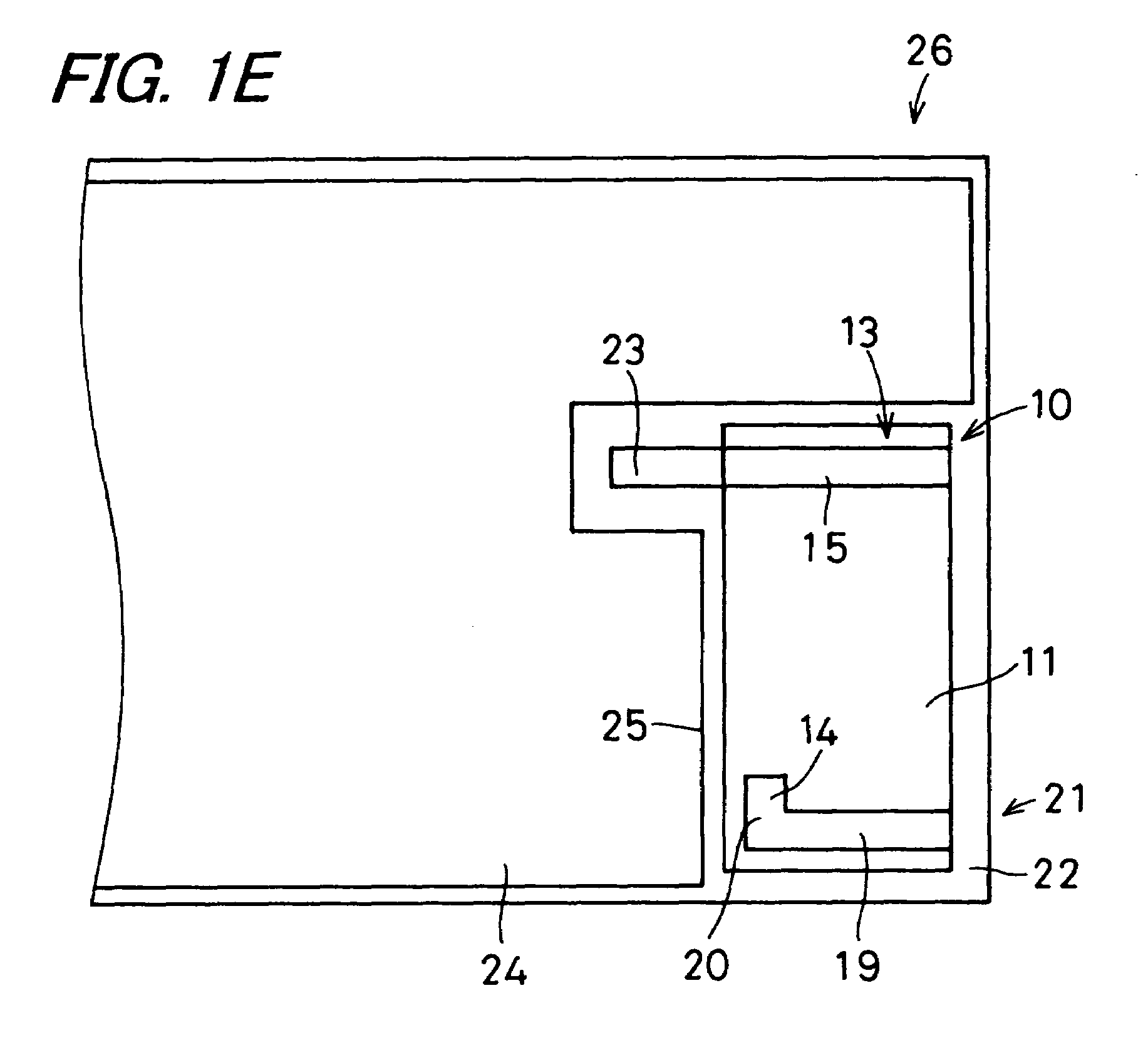
[0077]In FIGS. 1A to 1E, a surface-mount type antenna 10 according to the invention comprises a base body 11, a feeding terminal 12 and a radiating electrode 13 having a radiating electrode terminating portion 14. The base body 11 is made of a substantially rectangular parallelepiped dielectric or magnetic material. The feeding terminal 12 is formed at one end side part 11a of one side surface a of the base body 11. The radiating electrode 13, to one end of which is connected the feeding terminal 12, is disposed such that its other end extends from one end side part 11a of one side surface a, through one end side part 11c of one principal surface b, to one end side part 11e of another side surface c; is then turned, at a midpoint of the one end side part 11e thereof, toward another end side part 11f of the other side surface c; is further turned toward another end side part 11d of one principal surface b; is then routed on the other end side part 11d of one principal surface b; exte...

second embodiment

[0091]In FIGS. 2A to 2E, a surface-mount type antenna 30 according to the invention comprises a base body 31, a feeding terminal 32 and a radiating electrode 33 having a radiating electrode terminating portion 34. The base body 31 is made of a substantially rectangular parallelepiped dielectric or magnetic material. The feeding terminal 32 is formed at one end side part 31a of one side surface a of the base body 31. The radiating electrode 33, to one end of which is connected the feeding terminal 32, is disposed such that its other end extends from one end side part 31a of one side surface a, through one end side part 31c of one principal surface b, to one end side part 31e of another side surface c; is then turned, at a midpoint of the one end side part 31e thereof, toward another end side part 31f of the other side surface c; is further turned; is then routed on the other end side part 31d of one principal surface b; is turned from a midpoint of the other end side part 31d of one ...

third embodiment

[0098]Next, in FIGS. 3A to 3E, a surface-mount type antenna 50 according to the invention comprises a base body 51, a feeding terminal 52 and a radiating electrode 53 having a radiating electrode terminating portion 54. The base body 51 is made of a substantially rectangular parallelepiped dielectric or magnetic material. The feeding terminal 52 is formed at one end side part 51a of one side surface a of the base body 51. The radiating electrode 53, to one end of which is connected the feeding terminal 52, is disposed such that its other end extends from one end side part 51a of one side surface a, through one end side part 51c of one principal surface b, to one end side part 51e of another side surface c; is then turned, at a midpoint of the one end side part 51e thereof, toward another end side part 51f of the other side surface c; is further turned and extends toward another end side part 51d of one principal surface b; is then routed from the other end side part 51d of one princ...


PUM


Abstract

An surface-mount type antenna includes a rectangular parallelepiped base body, a feeding terminal formed at one-end-side part of one side surface thereof, and a radiating electrode, to one end of which is connected the feeding terminal, disposed such that its other end is routed from one-end-side part of one side surface, through one-end-side part of one principal surface, to another-end-side part of one principal surface, and extends from the other-end-side part to the one end side part parallelly with a ridge of the base body, and is eventually formed into an open end. An antenna apparatus is constructed by mounting the surface-mount type antenna on a mounting substrate having a feeding electrode and a ground conductor layer with a linear side edge located near the feeding electrode, with the ridge of the base body arranged parallel to the linear side edge of the ground conductor layer.

Description

BACKGROUND OF THE INVENTION[0001]1. Field of the Invention[0002]The present invention relates to a surface-mount type antenna which is a compact antenna, and an antenna apparatus for use in mobile communication apparatus such as a cellular phone.[0003]2. Description of the Related Art[0004]Recently, in keeping with rapid advancement of down-sized, lightweight, and high-performance mobile communication equipment such as a cellular phone, miniaturization and high performance have come to be increasingly demanded of an antenna which constitutes such equipment. To meet such demands, for example, a surface-mount type antenna has hitherto been developed.[0005]Now, a surface-mount type antenna of conventional design and an antenna apparatus incorporating the antenna will be described with reference to a perspective view shown in FIG. 10.[0006]In FIG. 10, reference numeral 200 represents a surface-mount type antenna. The surface-mount type antenna 200 is mounted on a mounting substrate 210,...

Claims


Application Information

Patent Timeline
Patent Type & Authority Patents(United States)
IPC IPC(8): H01Q1/38H01Q1/24H01Q1/12H01Q1/22H01Q9/04H01Q9/42
CPCH01Q1/12H01Q1/22H01Q9/0457H01Q9/0407H01Q1/2283H01Q1/24
Inventor IKUTA, TAKANORISATO, AKINORIWATADA, KAZUOMURAKAWA, SHUNICHI
Owner KYOCERA CORP
Why Eureka
Try Eureka