Semiconductor laser diode device and method of fabrication thereof
a laser diode and semiconductor technology, applied in the direction of lasers, semiconductor lasers, optical resonator shape and construction, etc., can solve the problems of difficult to provide different grating depths, produce sufficient degree of difference, and difficult control processes, so as to reduce the degree of wavelength chirping, reduce the transmission limit distance, and ensure the stability of single-mode oscillation.
- Summary
- Abstract
- Description
- Claims
- Application Information
AI Technical Summary
Benefits of technology
Problems solved by technology
Method used
Image
Examples
first preferred embodiment
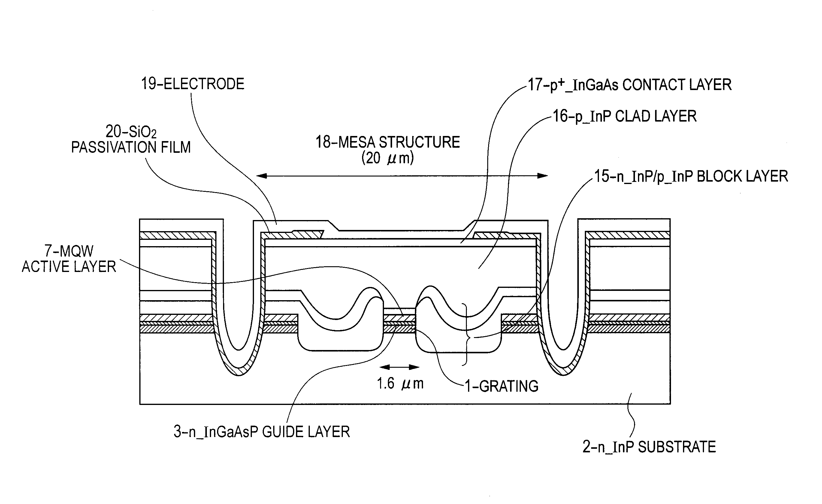
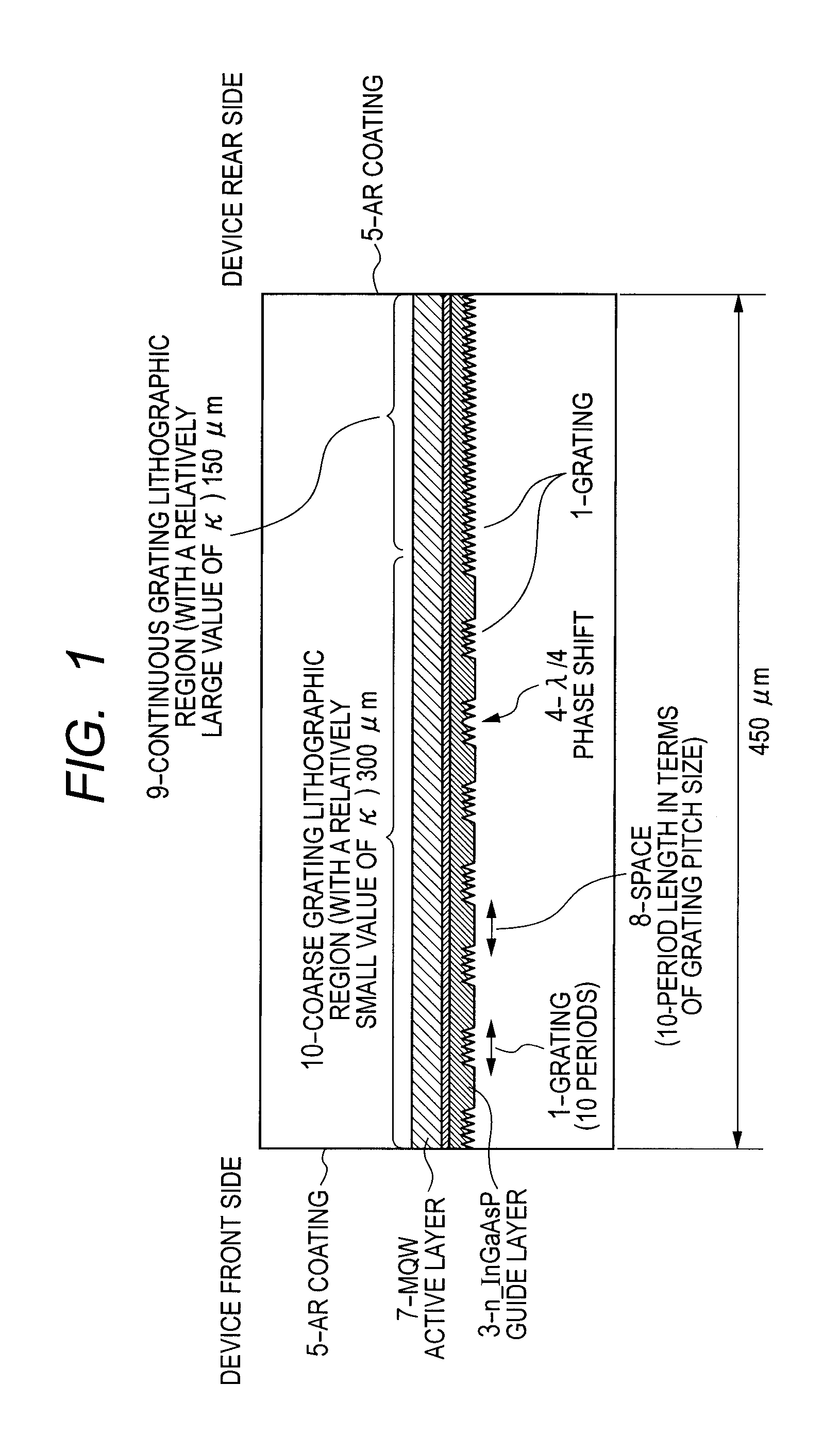
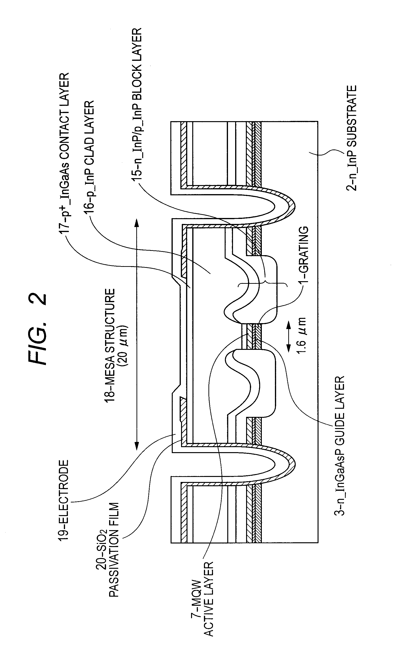
[0059]Referring to FIG. 1, there is shown a configuration of a DFB-LD device according to a first preferred embodiment of the present invention. In FIG. 1, a longitudinal cross-section parallel to the optical waveguide axial direction of the DFB-LD device is illustrated schematically. In a device front region of an optical waveguide according to the first preferred embodiment of the present invention, a grating 1 is formed to have ten periods, followed by a no-grating space part having a length of ten-period space, and an alternately repetitive pattern of the grating 1 and no-grating space part is provided (coarse grating lithographic region 10). The no-grating space part, which is indicated as “Space” with reference numeral 8 in FIG. 1, has a uniform refractive index. As a device rear region, there is provided a continuous grating lithographic region 9 of an ordinary type (continuous grating periodic region without partial missing of grating lines).
[0060]The average density of coar...
second preferred embodiment
[0099]Then, the following describes a second preferred embodiment of the present invention. Referring to FIG. 6, there is shown a configuration of a DFB-LD device according to the second preferred embodiment of the present invention. In FIG. 6, a longitudinal cross-section parallel to the optical waveguide axial direction of the DFB-LD device is illustrated schematically. According to the second preferred embodiment of the present invention, the device length L is 450 μm as in the case of the first preferred embodiment mentioned above, and a λ / 4 phase shift part 4 is disposed at a position of 300 λm from the device front end.
[0100]In the second preferred embodiment of the present invention, a coarse grating lithographic region 10 is provided in a length of 350 λm across the λ / 4 phase shift part 4 on the device front side. Further, in the coarse grating lithographic region 10 in the second preferred embodiment, there is formed an alternately repetitive pattern of a grating 1 having f...
third preferred embodiment
[0105]Then, the following describes a third preferred embodiment of the present invention. Referring to FIG. 7, there is shown a configuration of a DFB-LD device according to the third preferred embodiment of the present invention. In FIG. 7, a longitudinal cross-section parallel to the optical waveguide axial direction of the DFB-LD device is illustrated schematically. In the third preferred embodiment, as shown in FIG. 7, a λ / 4 phase shift part is not employed, differently from the case of the first preferred embodiment illustrated in FIG. 1. The other configurational features of the third preferred embodiment are the same as those of the first preferred embodiment in FIG. 1.
[0106]In the third preferred embodiment, a coarse grating lithographic region 10 is provided with an alternately repetitive pattern of a grating 1 having ten periods and a no-grating space part 8 (having a length of ten-period space). Note that, in the length of the space part 8, a factor of correction is incl...
PUM
 Abstract
Description
Claims
Application Information
 - R&D
- Intellectual Property
- Life Sciences
- Materials
- Tech Scout
- Unparalleled Data Quality
- Higher Quality Content
- 60% Fewer Hallucinations
Browse by: Latest US Patents, China's latest patents, Technical Efficacy Thesaurus, Application Domain, Technology Topic, Popular Technical Reports.
© 2025 PatSnap. All rights reserved.Legal|Privacy policy|Modern Slavery Act Transparency Statement|Sitemap|About US| Contact US: help@patsnap.com


