Valve structure of shock absorber

a valve structure and shock absorber technology, applied in the direction of shock absorbers, vibration dampers, springs/dampers, etc., can solve the problems of difficulty in satisfying ride comfort and stability simultaneously, and achieve the effect of satisfying ride comfort and stability of vehicles

Inactive Publication Date: 2013-06-06
HL MANDO CORP
View PDF9 Cites 22 Cited by
  • Summary
  • Abstract
  • Description
  • Claims
  • Application Information

AI Technical Summary

Benefits of technology

[0010]Therefore, it is an aspect of the present invention to provide a valve structure of a shock absorber which includes a main piston valve generating damping force varied according to moving velocity of a piston and a sub piston valve generating damping force varied according to frequency and thus simultaneously satisfies ride comfort and stability of a vehicle.

Problems solved by technology

Such damping force changed only according to the change of the velocity of the piston is equal in various road surface states, and may thus cause a difficulty of satisfying ride comfort and stability simultaneously.

Method used


Image

  • Valve structure of shock absorber
  • Valve structure of shock absorber
  • Valve structure of shock absorber

Examples


Embodiment Construction

[0022]Reference will now be made in detail to the embodiments of the present invention, examples of which are illustrated in the accompanying drawings, wherein like reference numerals refer to like elements throughout.

[0023]Hereinafter, a valve structure of a shock absorber in accordance with an embodiment of the present invention will be described with reference to the accompanying drawings.

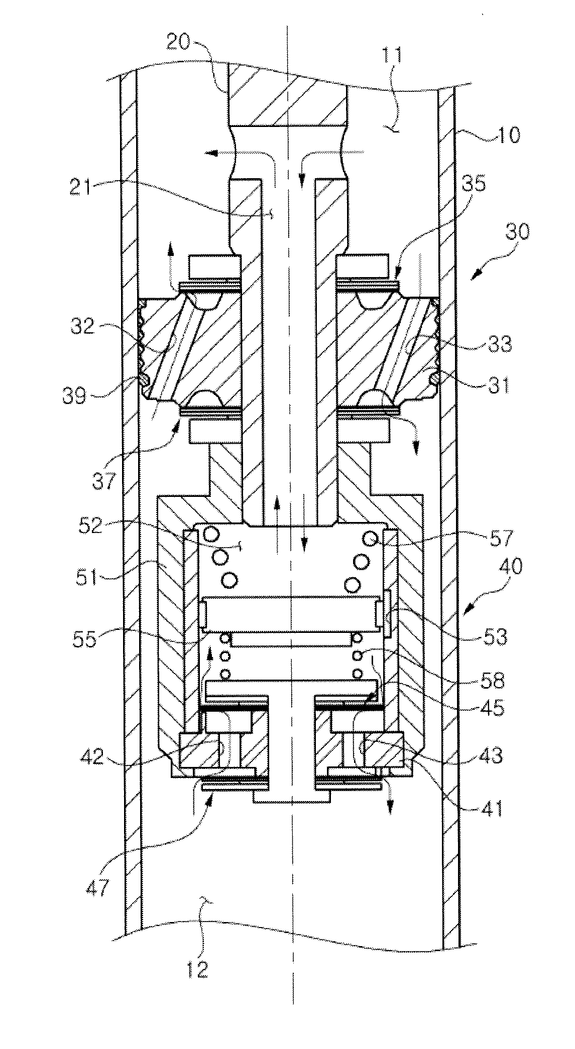
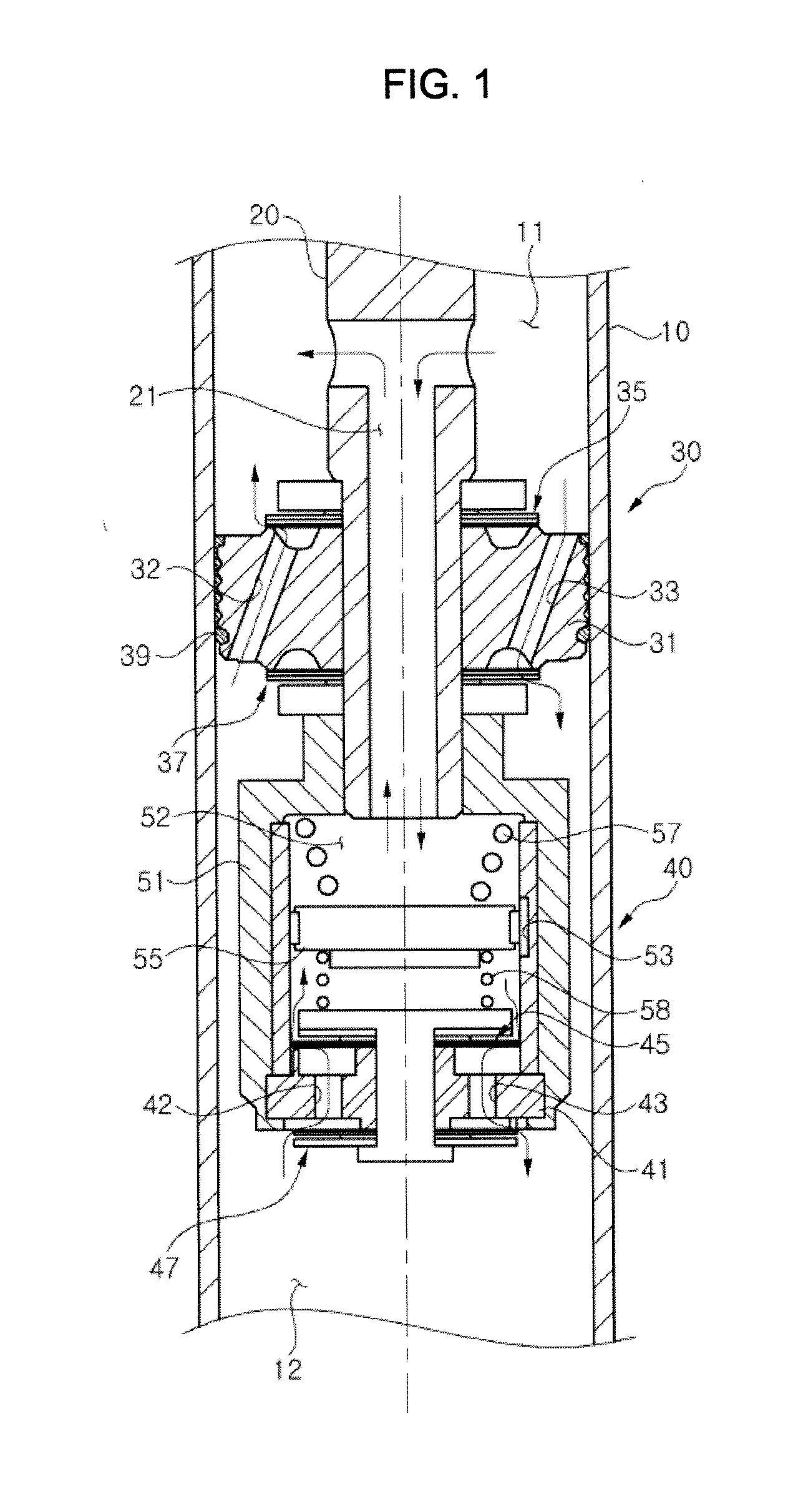
[0024]As shown in FIG. 1, the shock absorber provided with the valve structure in accordance with the embodiment of the present invention includes a cylinder 10 having a nearly cylindrical shape and filled with a working fluid, such as oil, and a piston rod 20 provided with one end located within the cylinder 10 and the other end extending to the outside of the cylinder 10.

[0025]The valve structure of the shock absorber in accordance with the embodiment of the present invention includes a main piston valve assembly 30 installed at the end of the piston rod 20 and operated to generate damping for...


PUM


Abstract

Disclosed herein is a valve structure of a shock absorber which respectively controls damping force at a low amplitude and a high amplitude when a piston valve is compressed and expanded and thus simultaneously satisfies ride comfort and stability of a vehicle. The valve structure of the shock absorber which has a cylinder filled with a working fluid and a piston rod provided with one end located within the cylinder and the other end extending to the outside of the cylinder, includes a main piston valve assembly installed at the end of the piston rod and operated to generate damping force varied according to moving velocity under the condition that the inside of the cylinder is divided into an upper chamber and a lower chamber, and a sub piston valve assembly moving together with the main piston valve assembly to generate damping force varied according to frequency.

Description

CROSS-REFERENCE TO RELATED APPLICATION[0001]This application claims the benefit of Korean Patent Application No. 2011-0051903, filed on May 31, 2011 in the Korean Intellectual Property Office, the disclosure of which is incorporated herein by reference.BACKGROUND[0002]1. Field[0003]Embodiments of the present invention relate to a valve structure of a shock absorber which respectively controls damping force at a low amplitude and a high amplitude when a piston valve is compressed and expanded and thus simultaneously satisfies ride comfort and stability of a vehicle.[0004]2. Description of the Related Art[0005]In general, a damping device damping impact or vibration applied to an axle from the road surface during driving to improve ride comfort is installed in a vehicle, and a shock absorber is used as one such damping device.[0006]The shock absorber is operated according to vibration of the vehicle corresponding to the state of the road surface, and damping force generated from the s...

Claims


Application Information

Patent Timeline
Patent Type & Authority Applications(United States)
IPC IPC(8): F16F9/512F16F9/34
CPCF16F9/3405F16F9/5126F16F9/34F16F9/342
Inventor YU, CHUN SUNG
Owner HL MANDO CORP
Why Eureka
Try Eureka