Seeding device and seeding method

a seeding device and seeding technology, applied in the direction of lighting and heating equipment, combustion types, instruments, etc., can solve the problem of reducing the amount of tracer particles of a small particle size to be supplied into the wind tunnel

Active Publication Date: 2015-06-25
HONDA MOTOR CO LTD
View PDF15 Cites 7 Cited by
  • Summary
  • Abstract
  • Description
  • Claims
  • Application Information

AI Technical Summary

Benefits of technology

[0028]With this configuration, a ring vortex is generated in the vicinity of the starting end of the jet flow from the seeder, and division and disappearance of such a ring vortex can be promoted without problems by the outside air introduced through the opening. This can promote the growth of the jet flow, i.e., the atomization, and so liquid particles of a large particle size that adhere to the inner wall of the tubular body can decrease in number, and accordingly liquid particles of a small particle size that are suitable for tracer increase in number. In this way, more tracer particles can be discharged.
[0029]In the present invention, the opening may be located in a longitudinal direction of the tubular body at a position of the starting end of the jet flow or at a position from the position closer to the tip end of the tubular body. This enables outside air to be introduced from the opening at the starting end of the jet flow or at a position closer to the tip end of the tubular body, and so the division and disappearance of a ring vortex in the jet flow can be promoted reliably.
[0030]A seeding method of the present invention comprises, disposing the seeding device according to the present invention in a wind tunnel, and then jetting out a jet flow containing liquid particles and gas from the seeder of the seeding device, thus supplying tracer particles into the wind tunnel. This can supply tracer particles into the wind tunnel while exerting the aforementioned effects from the seeding device.

Problems solved by technology

However, the amount of tracer particles of a small particle size to be supplied into the wind tunnel unfortunately decreases.

Method used


Image

  • Seeding device and seeding method
  • Seeding device and seeding method
  • Seeding device and seeding method

Examples


Embodiment Construction

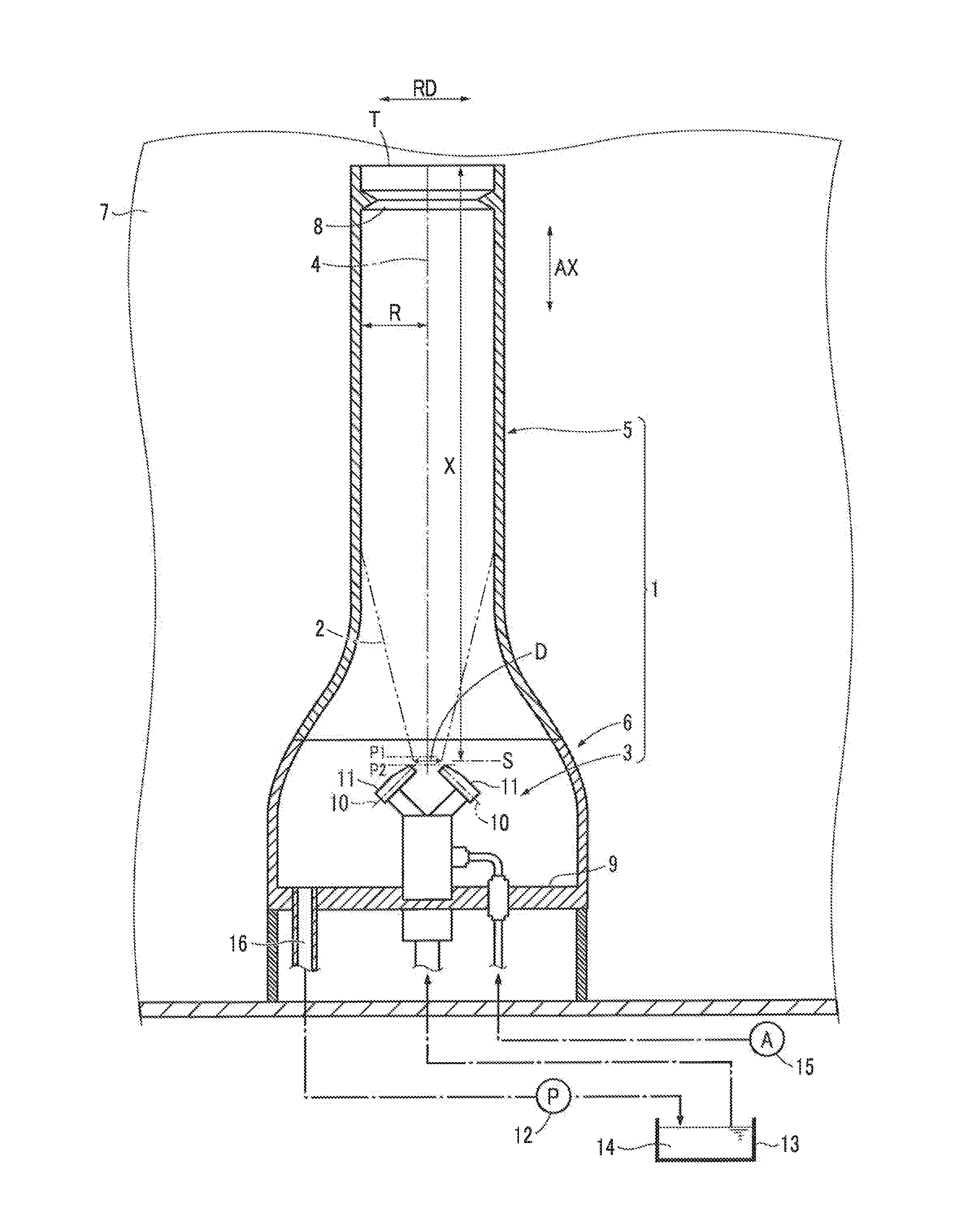
[0037]The following describes embodiments of the present invention, with reference to the drawings. As illustrated in FIG. 1, a seeding device 1 of the present embodiment includes a seeder 3 that jets out a jet flow 2 containing oil particles and air therein, and is configured to discharge tracer particles made up of the oil particles.

[0038]The seeding device 1 includes a tubular body 5 that surrounds the jet flow 2 from the seeder 3 along a center axis 4 in the jetting direction of the jet flow 2 so that some of the oil particles in the jet flow 2 adhere to the inner wall thereof, and an oil receiver 6 that receives an oil flow that is the collection of the oil particles adhered to the tubular body 5. In FIG. 1, the direction AX represents the direction of the jet flow 2 and the center axis 4 of the tubular body 5, and the direction RD represents the radial direction of the jet flow 2 and the tubular body 5.

[0039]The tubular body 5 is configured to adjust so that the oil particles ...


PUM


Abstract

A seeding device 1 includes a seeder 3 that jets out a jet flow 2 containing oil particles and gas therein, and a tubular body 5, 23 surrounding the jet flow 2. The distance X from a starting end S of the jet flow 2 to the tip end T of the tubular body 5, 23 is set so that the progressing rate of atomization of the oil particles at the tip end T of the tubular body 5, 23 is a predetermined rate or less.

Description

BACKGROUND OF THE INVENTION[0001]1. Field of the Invention[0002]The present invention relates to a seeding device including a seeder from which a jet flow including liquid particles and gas is jetted, the seeding device supplying tracer particles made up of such liquid particles into a wind tunnel, and such a seeding method.[0003]2. Description of the Related Art[0004]Conventionally known seeding devices of such a type include a device provided with a seeder from which a jet flow containing oil particles and air is jetted, and a collision surface intersecting the jetting direction of the jet flow (see Patent Literature 1, for example).[0005]Such a seeding device is configured so that oil particles of a large particle size collide with the collision surface without being carried with the air deflecting due to the collision surface, and are captured by the collision surface. On the other hand, oil particles of a small particle size are carried with the air deflecting due to the collis...

Claims


Application Information

Patent Timeline
Patent Type & Authority Applications(United States)
IPC IPC(8): B05B7/04B05B7/00
CPCB05B7/0012B05B7/0483G01M9/067B05B1/26
Inventor NAKAJIMA, MASATOFUKUCHI, YUICHI
Owner HONDA MOTOR CO LTD
Why Eureka
Try Eureka