This helps you quickly interpret patents by identifying the three key elements:
Problems solved by technology
Method used
Benefits of technology
[0008]The present disclosure is made in view of the above disadvantage, and it is an objective of the present disclosure to provide a method for manufacturing a t
Problems solved by technology
Particularly, a selectable material of the liquid seal agent is limited to, for example, a material that is not deteriorated even upon
Method used
Image
Click on the blue label to locate the original text in one second.
Reading with bidirectional positioning of images and text.
Examples
Example
First Embodiment
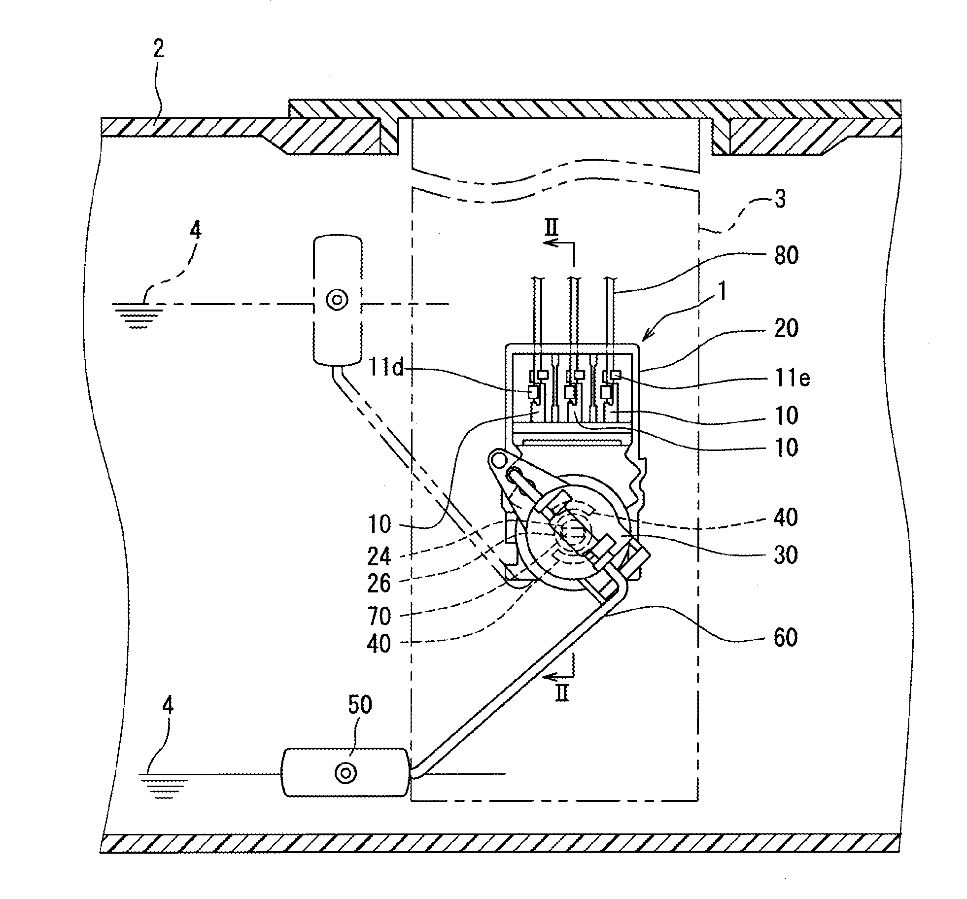
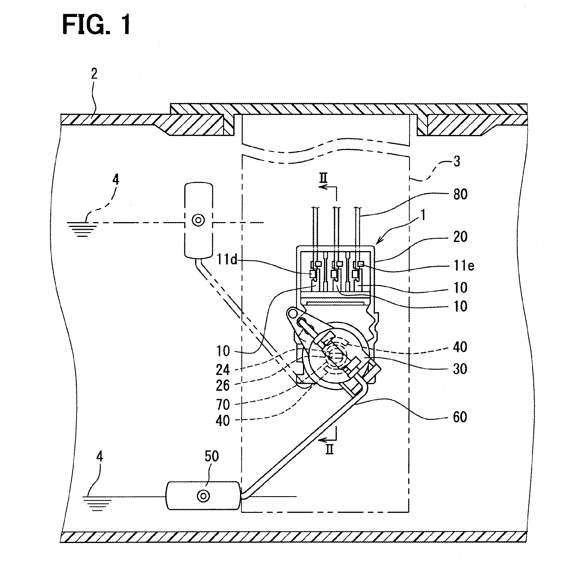
[0029]As shown in FIG. 1, terminals 10 of the present embodiment are used in a liquid level sensing apparatus 1.
(Structure of Liquid Level Sensing Apparatus)
[0030]First of all, a structure of the liquid level sensing apparatus 1 will be described in detail.
[0031]The liquid level sensing apparatus 1 is received in a fuel tank 2, which stores liquid fuel in a vehicle. The liquid level sensing apparatus 1 is supported, for example, by a fuel pump module 3 at a position, at which the liquid level sensing apparatus 1 is immersed in the fuel in the fuel tank 2. In this supported state, the liquid level sensing apparatus 1 senses a level of a surface 4 of the fuel in the fuel tank 2.
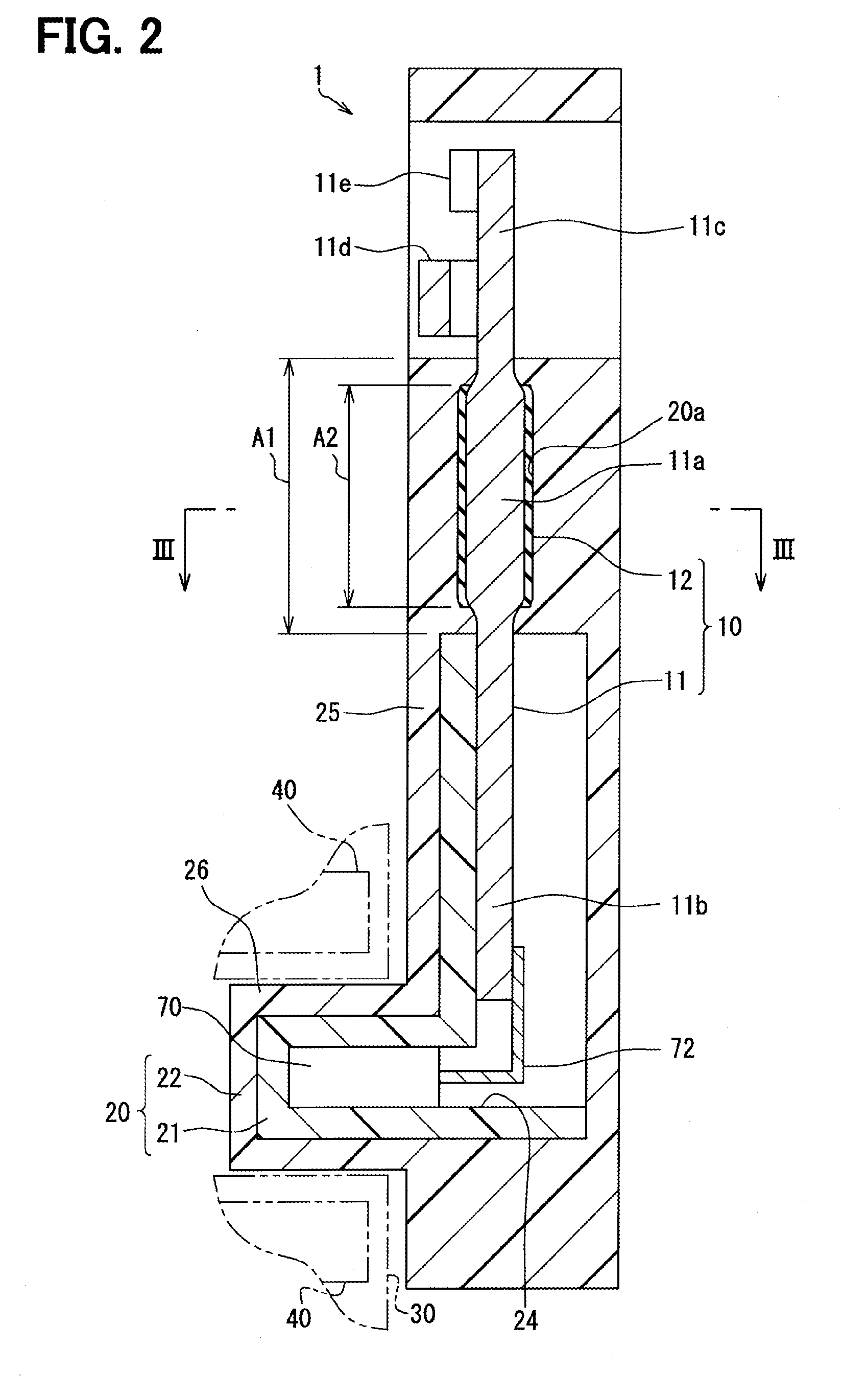
[0032]As indicated in FIGS. 1 and 2, the liquid level sensing apparatus 1 includes a housing 20, a plurality of terminals 10, a magnet holder 30, a plurality of magnets 40, a float 50, a float arm 60 and a Hall IC 70.
[0033]As shown in FIG. 2, the housing 20 includes an inner case 21 and an outer...
Example
Second Embodiment
[0058]In the first embodiment, the seal film 12 is formed in the intermediate portion 11a and is not formed in the the connecting portions 11f. In contrast, according to the present embodiment, the seal film 12 is also formed in each connecting portion 11f in addition to the intermediate portion 11a.
[0059]As discussed above, the cross section 11s of the intermediate portion 11a is the circular shape, and the cross sections 11bs, 11cs of the one end portion 11b and the other end portion 11c are rectangular shapes, respectively. The cross section of each of the connecting portions 11f, each of which connects between the corresponding one of the one end portion 11b and the other end portion 11c to the intermediate portion 11a, is configured such that the shape of the cross section of the connecting portion 11f progressively changes from the shape of the cross section of the corresponding one of the one end portion 11b and the other end portion 11c to the shape of the ...
PUM
Property
Measurement
Unit
Electrical conductivity
aaaaa
aaaaa
Abstract
A method for manufacturing a terminal includes: an electrically conductive member that has an electrical connection, which is formed at an end portion of the electrically conductive member; and a seal film that is formed in a surface of a predetermined portion of the electrically conductive member, which is other than the electrical connection. In the method for manufacturing, the electrically conductive member is formed by processing an end portion of a rounded rod, which has a cross section having an arcuate shape, into a planar shape to form the electrical connection. Furthermore, a liquid seal agent is coated on a predetermined portion of the rounded rod, which is other than the end portion. Then, the coated liquid seal agent is solidified to form the seal film.
Description
CROSS REFERENCE TO RELATED APPLICATION[0001]The present disclosure is based on and incorporates herein by reference Japanese Patent Application No. 2012-256972 filed on Nov. 23, 2012 and Japanese Patent Application No. 2013-125968 filed on Jun. 14, 2013.TECHNICAL FIELD[0002]The present disclosure relates to a terminal, to which an external electrical conductor, such as a lead wire, is connected, and a method for manufacturing the terminal.BACKGROUND ART[0003]The Patent Literature 1 discloses a terminal, which is arranged to extend from an inside to an outside of a housing made of a resin material in a liquid level sensing apparatus placed in a fuel tank. A seal film is formed in a portion of the terminal, which contacts the housing, to limit intrusion of the fuel into the inside of the housing through a gap between the terminal and the housing. Specifically, a liquid seal agent is coated on a surface of the terminal, and this coated liquid seal agent is solidified to form the seal f...
Claims
Application Information
Patent Timeline
Application Date:The date an application was filed.
Publication Date:The date a patent or application was officially published.
First Publication Date:The earliest publication date of a patent with the same application number.
Issue Date:Publication date of the patent grant document.
PCT Entry Date:The Entry date of PCT National Phase.
Estimated Expiry Date:The statutory expiry date of a patent right according to the Patent Law, and it is the longest term of protection that the patent right can achieve without the termination of the patent right due to other reasons(Term extension factor has been taken into account ).
Invalid Date:Actual expiry date is based on effective date or publication date of legal transaction data of invalid patent.