

Suspension and traction system for vehicles
A traction system and vehicle technology, applied in the direction of suspension, elastic suspension, vehicle components, etc., can solve problems such as system difficulties, and achieve the effect of simplifying the cooling system, improving the initial adhesion, and simplifying the electrical connection
- Summary
- Abstract
- Description
- Claims
- Application Information
AI Technical Summary
Problems solved by technology
Method used
Image

Examples
Embodiment Construction
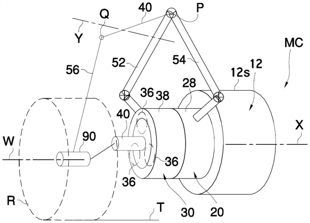
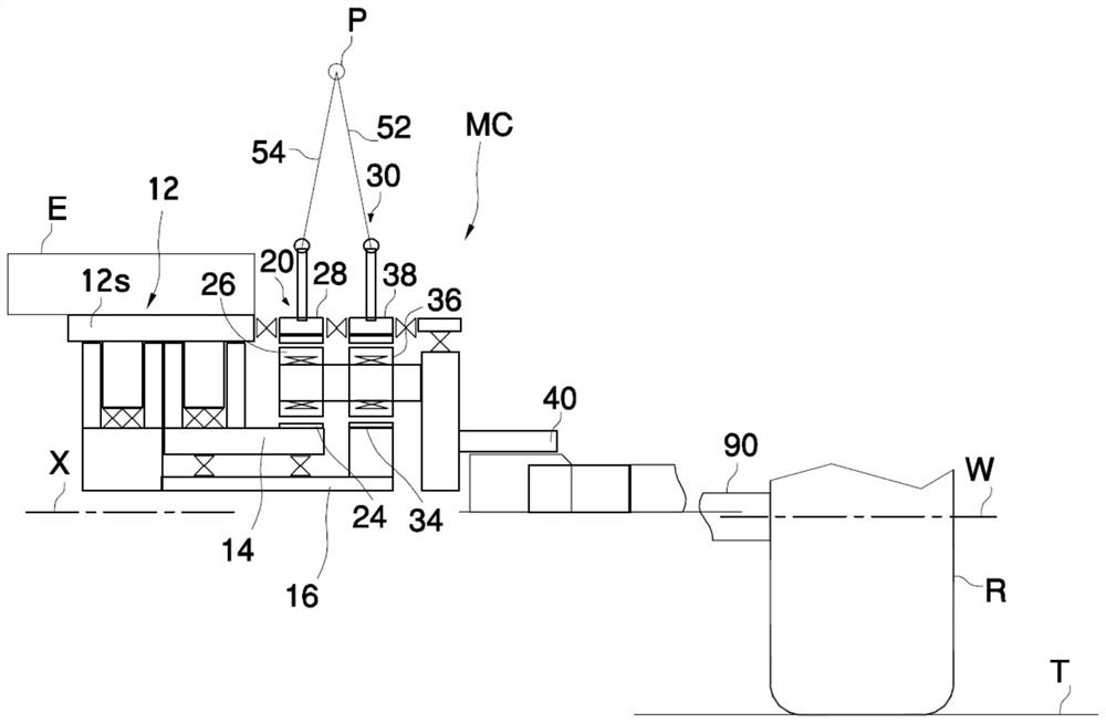
[0070] The system MC shown serves to rotate a propulsion element in the form of a wheel R. The wheels R move an associated vehicle (not shown) by rolling over the terrain T. System MC is for example duplicated on all wheels of the vehicle.
[0071] System MC includes a rotating electric motor 12 formed by a common stator 12S and two independent rotors 14 , 16 . The electrical part of the electric motor 12 is, for example, of known type.
[0072] The rotors 14, 16 are coaxial and have a common axis of rotation indicated by X, which is fixed relative to the frame.
[0073] The rotors 14, 16 may also be mounted one inside the other (for example, they are two concentric sleeves) and transmit torque from the motor to the sun gear 24 and the sun gear belonging to the respective planetary gear mechanism 20, 30 respectively. 34.
[0074] The planetary gear mechanism 20 (30) comprises, in known manner, a central sun gear 24 (34) meshing with a planetary gear 26 (36), which in turn ...
PUM
 Abstract
Description
Claims
Application Information