Reactive Orthotropic Lattice Diffuser for Noise Reduction

Active Publication Date: 2015-09-17
NASA
View PDF18 Cites 18 Cited by
  • Summary
  • Abstract
  • Description
  • Claims
  • Application Information

AI Technical Summary

Benefits of technology

[0007]At least a portion of the inboard and/or outboard end surfaces, and/or the inboard and outboard end portions of the upper or lower side of the flap include a substantially porous surface that is acoustically connected to chambers (or passageways) that are disposed within the elongated flap structure. Noise generated by the noise source enters the internal chambers through the openings, and a portion of that noise is absorbed to thereby reduce the amount of noise that would otherwise be transmitted to the surrounding environment. If the chambers are sufficiently small in diameter, are terminated within the flap structure, and are not allowed to communicate with other internal chambers, the structure forms a local-reacting liner. If the chambers are large

Problems solved by technology

The upper and lower sides define inboard and outboard end portions adjacent the inboard and outboard ends, respectively, that tend to experience significant local hydrodyna

Method used


Image

  • Reactive Orthotropic Lattice Diffuser for Noise Reduction
  • Reactive Orthotropic Lattice Diffuser for Noise Reduction
  • Reactive Orthotropic Lattice Diffuser for Noise Reduction

Examples


Example

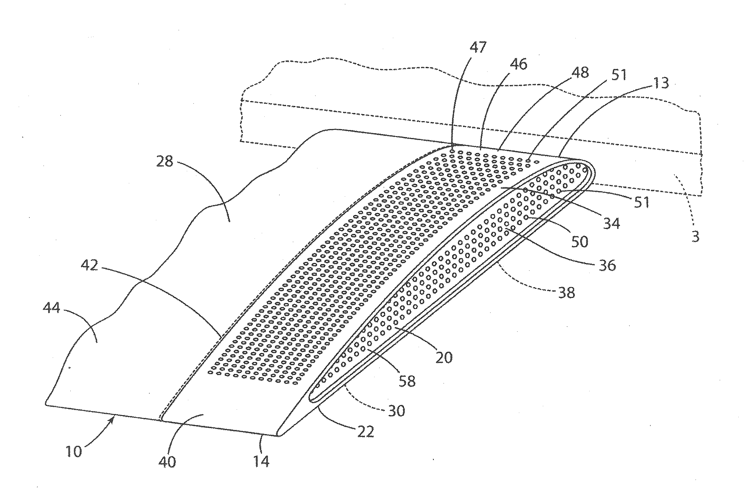
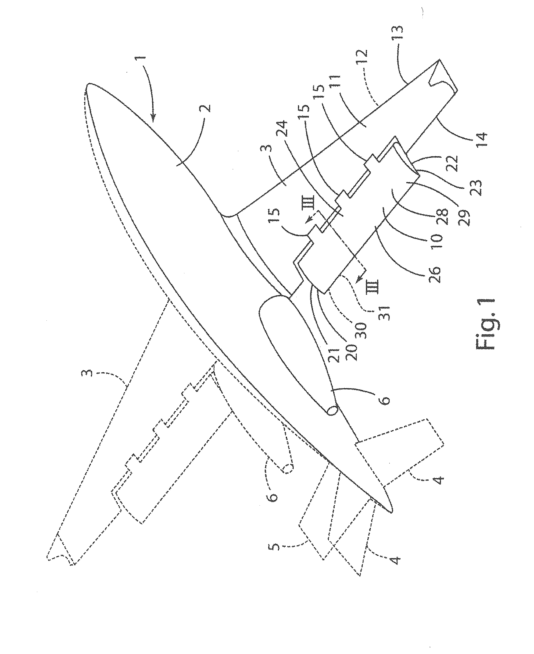
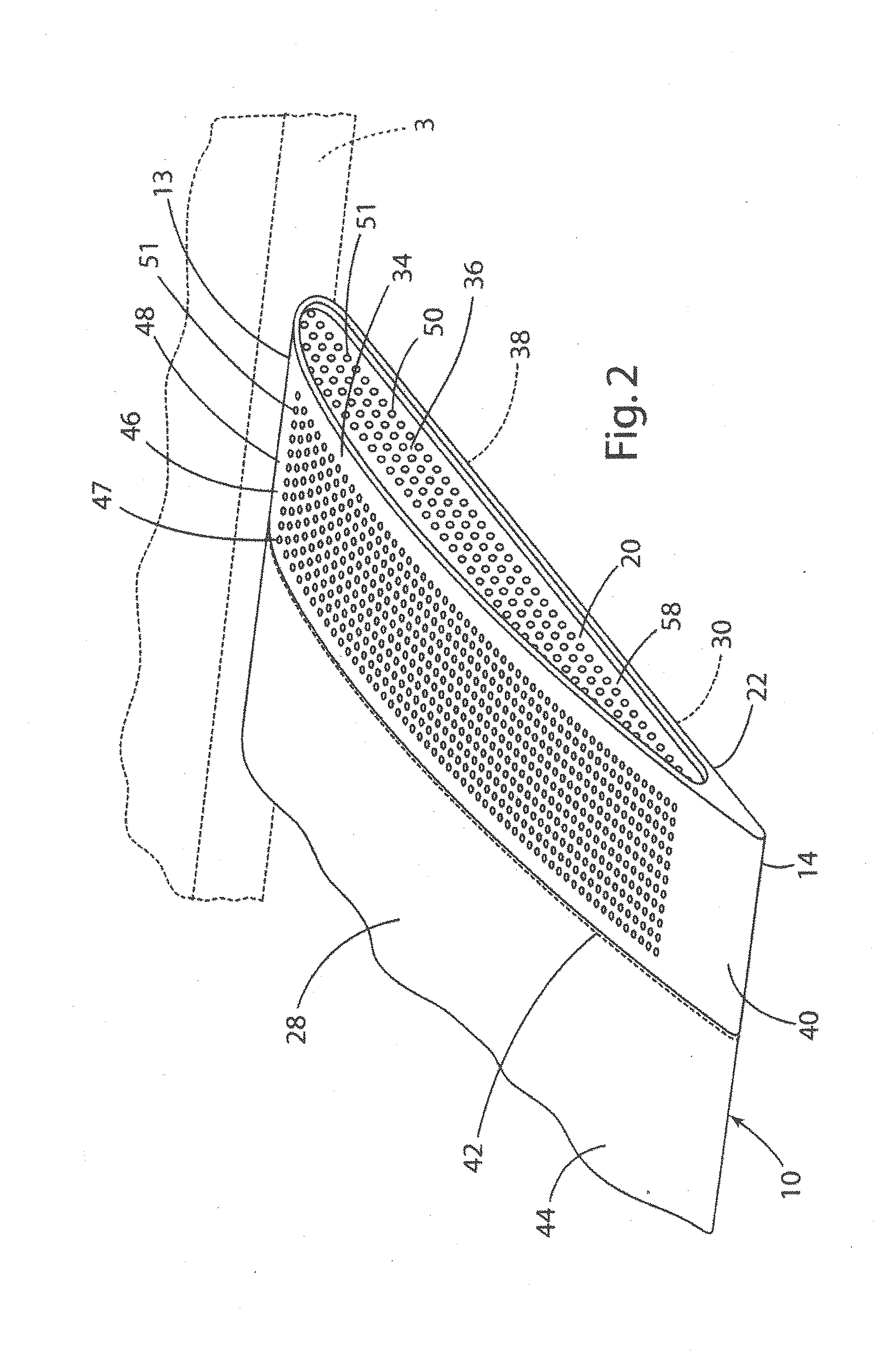
[0021]For purposes of description herein, the terms “upper,”“lower,”“right,”“left,”“rear,”“front,”“vertical,”“horizontal,” and derivatives thereof shall be related to the invention as oriented in FIG. 1. However, it is to be understood that the invention may assume various alternative orientations, except where expressly specified to the contrary. It is also to be understood that the specific devices and processes illustrated in the attached drawing, and described in the following specification are simply exemplary embodiments of the inventive concepts defined in the appended claims. Furthermore, references to specific items or features (e.g. a wing structure, leading edge slat, and slat cove filler) shall not be construed as limiting the item or feature to one-piece or multi-piece items or features. Hence, specific dimensions and other physical characteristics relating to the embodiments disclosed herein are not to be considered as limiting, unless the claims expressly state otherw...


PUM


Abstract

An orthotropic lattice structure interconnects porous surfaces of the flap with internal lattice structured perforations to equalize the steady pressure field on the flap surfaces adjacent to the end and to reduce the amplitude of the fluctuations in the flow field near the flap end. The global communication that exists within all of the perforations provides the mechanism to lessen the pressure gradients experienced by the end portion of the flap. In addition to having diffusive effects (diffusing the incoming flow), the three-dimensional orthogonal lattice structure is also reactive (acoustic wave phase distortion) due to the interconnection of the perforations.

Description

CROSS-REFERENCE TO RELATED APPLICATIONS[0001]This is a continuation-in-part of U.S. patent application Ser. No. 13 / 417,347 titled “Flap Side Edge Liners for Airframe Noise Reduction,” filed on Mar. 12, 2012. Further, this application is related to co-pending U.S. patent application Ser. No. 13 / 417,349, filed Mar. 12, 2012, titled “Landing Gear Door Liners for Airframe Noise Reduction,” and U.S. patent application Ser. No. 13 / 417,351, filed Mar. 12, 2012, titled “External Acoustic Liners for Multi-Functional Aircraft Noise Reduction.” This application further claims the benefits of U.S. Provisional Application Nos. 61 / 451,727, filed on March 11, 2011; 61 / 451,730 filed on Mar. 11, 2011; 61 / 451,735 filed on Mar. 11, 2011; and 61 / 597,282, filed on Feb. 10, 2012, the entire contents of all incorporated herein by reference.STATEMENT REGARDING FEDERALLY SPONSORED RESEARCH OR DEVELOPMENT[0002]The invention described herein was made by an employee of the United States Government and may be m...

Claims


Application Information

Patent Timeline
IPC IPC(8): B64C1/40
CPCB64C1/40B64C2230/14B64C2230/22B64C9/18B64C21/10B64C23/005B64C2230/24Y02T50/30Y02T50/10
Inventor KHORRAMI, MEHDI R.
Owner NASA
Why Eureka
Try Eureka