Fixed type constant velocity universal joint

a constant velocity, universal joint technology, applied in the direction of yielding couplings, couplings, rotary machine parts, etc., can solve the problems of insufficient effective track length and inability to form high operating angles, and achieve excellent strength and durability, long life, and high operating angles.

Active Publication Date: 2015-11-05
NTN CORP
View PDF4 Cites 1 Cited by
  • Summary
  • Abstract
  • Description
  • Claims
  • Application Information

AI Technical Summary

Benefits of technology

[0028]According to the one embodiment of the present invention, it is possible to attain the fixed type constant velocity universal joint that is suppressed in torque loss and heat generation, markedly enhanced in efficiency, has a prolonged life due to the less heat generation, and is compactified. The fixed type constant velocity universal joint is also capable of forming high operating angles, excellent in strength and durability at the high operating angles, and is suited to reduce noise, vibration, and harshness (NVH) of a vehicle as well.

Problems solved by technology

This is because the effective track length becomes insufficient.
As a result, there arises a problem that high operating angles cannot be formed.

Method used


Image

  • Fixed type constant velocity universal joint
  • Fixed type constant velocity universal joint
  • Fixed type constant velocity universal joint

Examples


Embodiment Construction

[0075]Embodiments of the present invention are described with reference to FIGS. 1 to 24.

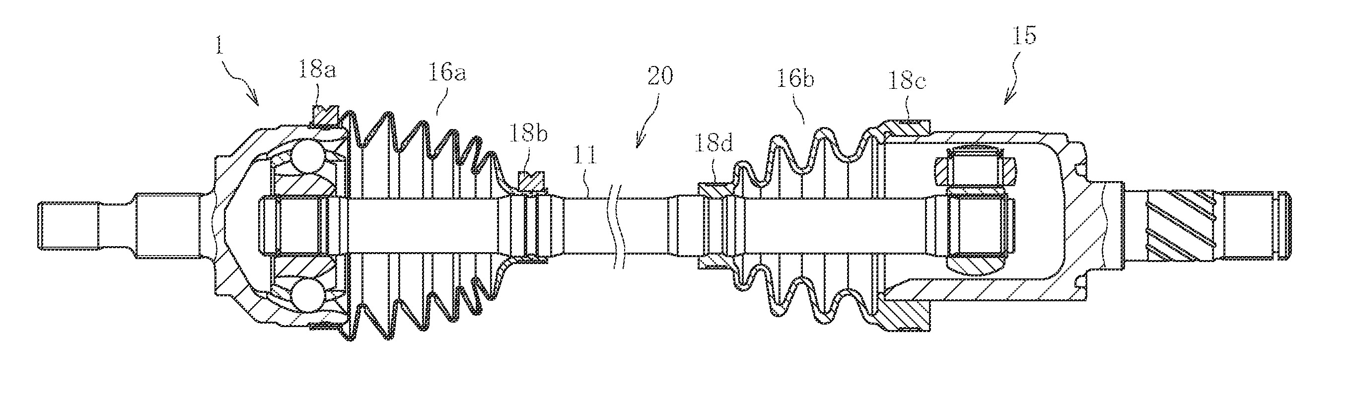
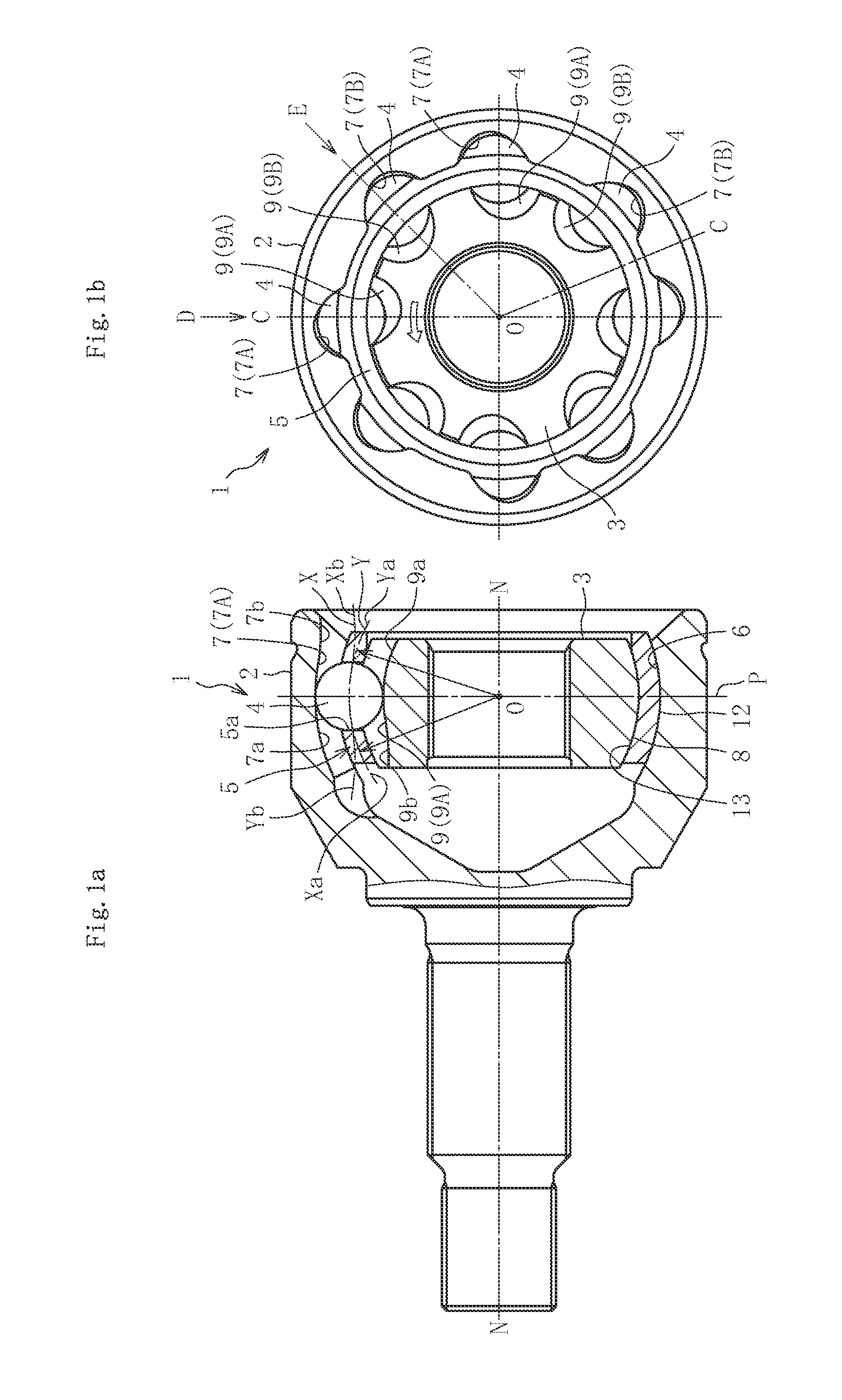
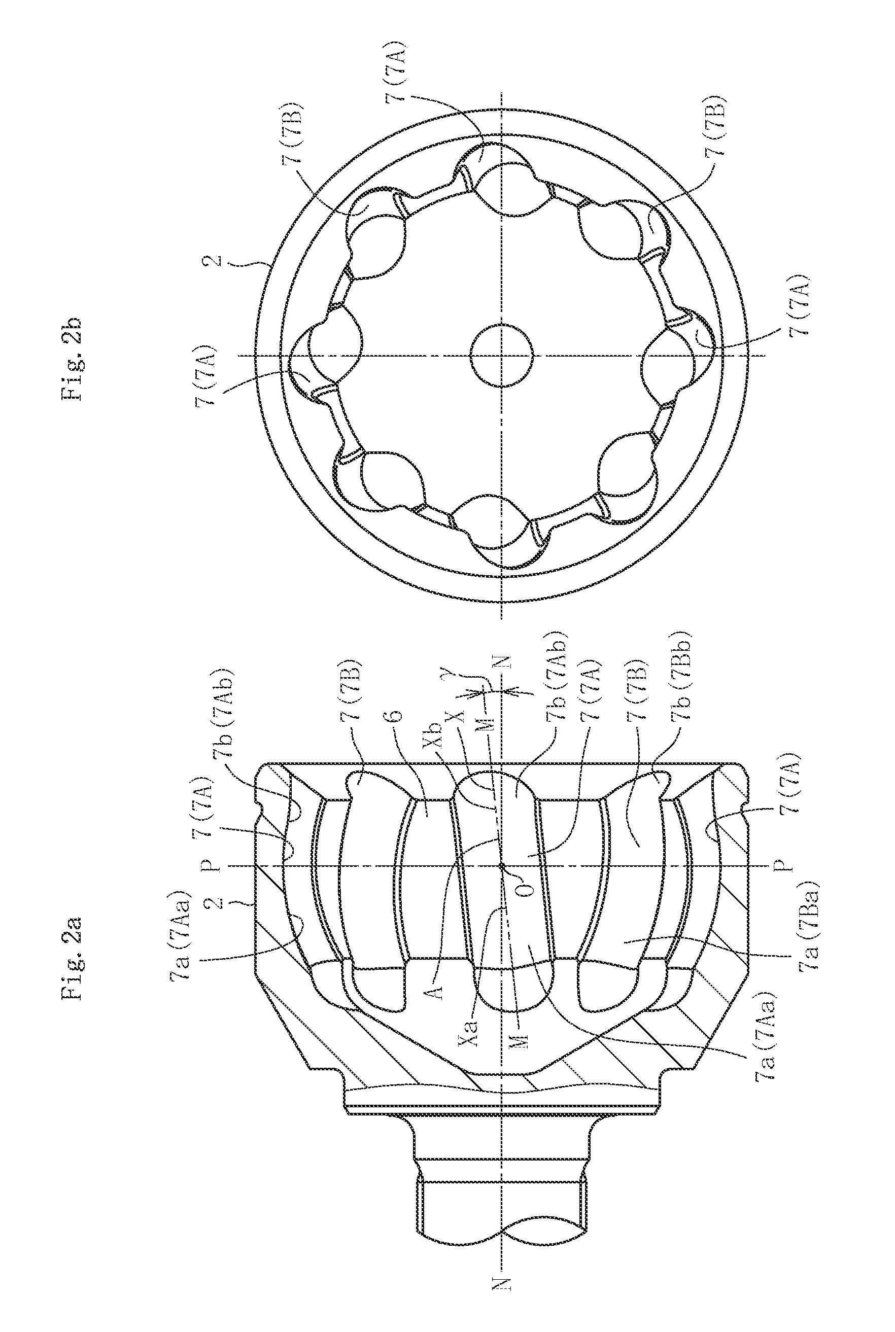
[0076]FIGS. 1 to 13 illustrate a first embodiment of the present invention. FIG. 1 illustrate a fixed type constant velocity universal joint according to the first embodiment. FIG. 1a is a partial vertical sectional view taken along the line C-O-C in FIG. 1b, and FIG. 1b is a right-hand side view of FIG. 1a. A constant velocity universal joint 1 mainly comprises an outer joint member 2, an inner joint member 3, balls 4, and a cage 5. As illustrated in FIGS. 1b, 2, and 3, respective eight track grooves 7 and 9 of the outer joint member 2 and the inner joint member 3 respectively comprise track grooves 7A and 7B and track grooves 9A and 9B that are inclined in a peripheral direction with respect to a joint axial line N-N and adjacent to each other in the peripheral direction with their inclination directions opposite to each other. Eight balls 4 are arranged in crossing portions of the paired trac...


PUM


Abstract

Provided is a fixed type constant velocity universal joint, in which: each of first track groove portions positioned on an interior side of an outer joint member includes an arc part having a curvature center that is positioned without being offset in an axial direction with respect to a joint center; the first track groove portions are inclined in a peripheral direction with respect to a joint axial line (N-N) and adjacent to each other in the peripheral direction with their inclination directions opposite to each other; each of second track groove portions positioned on an opening side is formed into a different shape from a shape of the each of the first track groove portions so as to increase an effective track length at a maximum operating angle; the each of the first track groove portions and the each of the second track groove portions are connected to each other at a position on the opening side with respect to the joint center; each of track grooves of an inner joint member is formed so as to be mirror-image symmetrical with corresponding one of paired track grooves of the outer joint member with respect to a plane including the joint center and being perpendicular to the joint axial line at an operating angle of 0°; and an axial clearance between the inner joint member and a cage is set to be larger than an axial clearance corresponding to a clearance between each of balls and each of the track grooves.

Description

TECHNICAL FIELD[0001]The present invention relates to a fixed type constant velocity universal joint, and more specifically, to a fixed type constant velocity universal joint to be used in a power transmission system of automobiles and various industrial machines, for allowing only angular displacement between two shafts on a driving side and a driven side.BACKGROUND ART[0002]For example, a plunging type constant velocity universal joint that is axially displaceable while forming an operating angle but forms a relatively small maximum operating angle is generally assembled on an inboard side (differential side) of an automotive front drive shaft. Further, a fixed type constant velocity universal joint that can form a large operating angle but is not axially displaceable is generally assembled on an outboard side (wheel side) of the automotive front drive shaft because the wheel is steered on the outboard side.[0003]FIG. 27 illustrate a Rzeppa type constant velocity universal joint 1...

Claims


Application Information

Patent Timeline
Patent Type & Authority Applications(United States)
IPC IPC(8): F16D3/223
CPCF16D2003/22309F16D3/223F16D3/2233F16D3/2245Y10S464/906
Inventor HIRUKAWA, HIROYASUFUJIO, TERUAKIYAMAZAKI, KENTA
Owner NTN CORP
Why Eureka
Try Eureka