Traction Switching Device

a switching device and traction technology, applied in the field of traction devices, can solve the problems of inconvenient operation, complex structure, and inability to meet the existing market demand, and achieve the effect of simple and reasonable traction

Active Publication Date: 2016-01-07
SHI FUYOU
View PDF1 Cites 4 Cited by
  • Summary
  • Abstract
  • Description
  • Claims
  • Application Information

AI Technical Summary

Benefits of technology

[0004]Aiming at the defects of prior art, the utility model provides a simple and reasonable traction switching device. By pulling the push-pull button while pressing the manual button, the traction switching device is fully locked; conversely, the traction switching device is unlocked by the push-pull button.

Problems solved by technology

Currently, the existing traction pulley braking switch is featured with complex and non-portable structure as well as inconvenient operation, which can not meet the existing market demand.
The technical proposal is characterized by complex structure and inconvenient operation, which can not meet the existing market demand.

Method used


Image

  • Traction Switching Device
  • Traction Switching Device
  • Traction Switching Device

Examples


Embodiment Construction

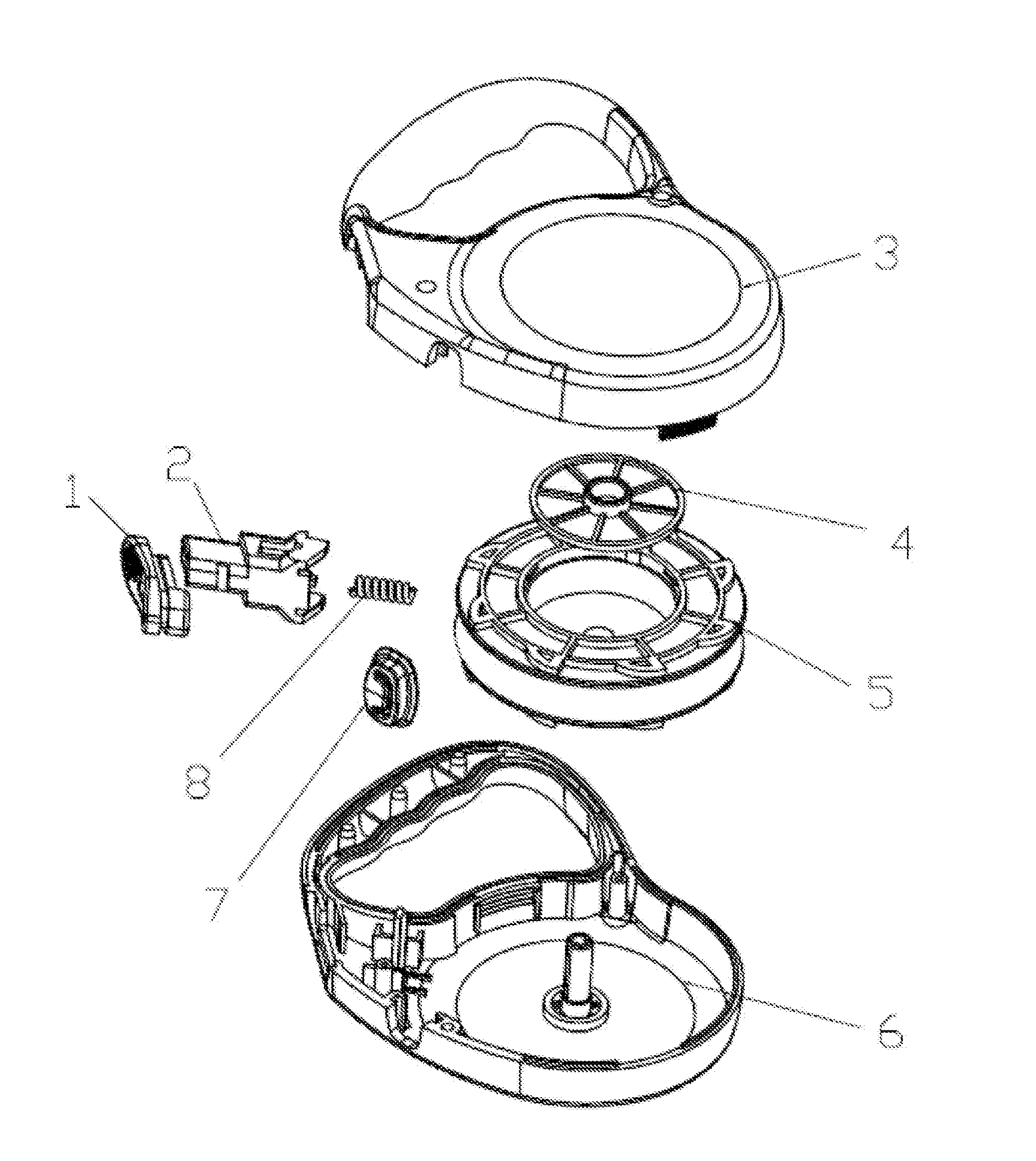
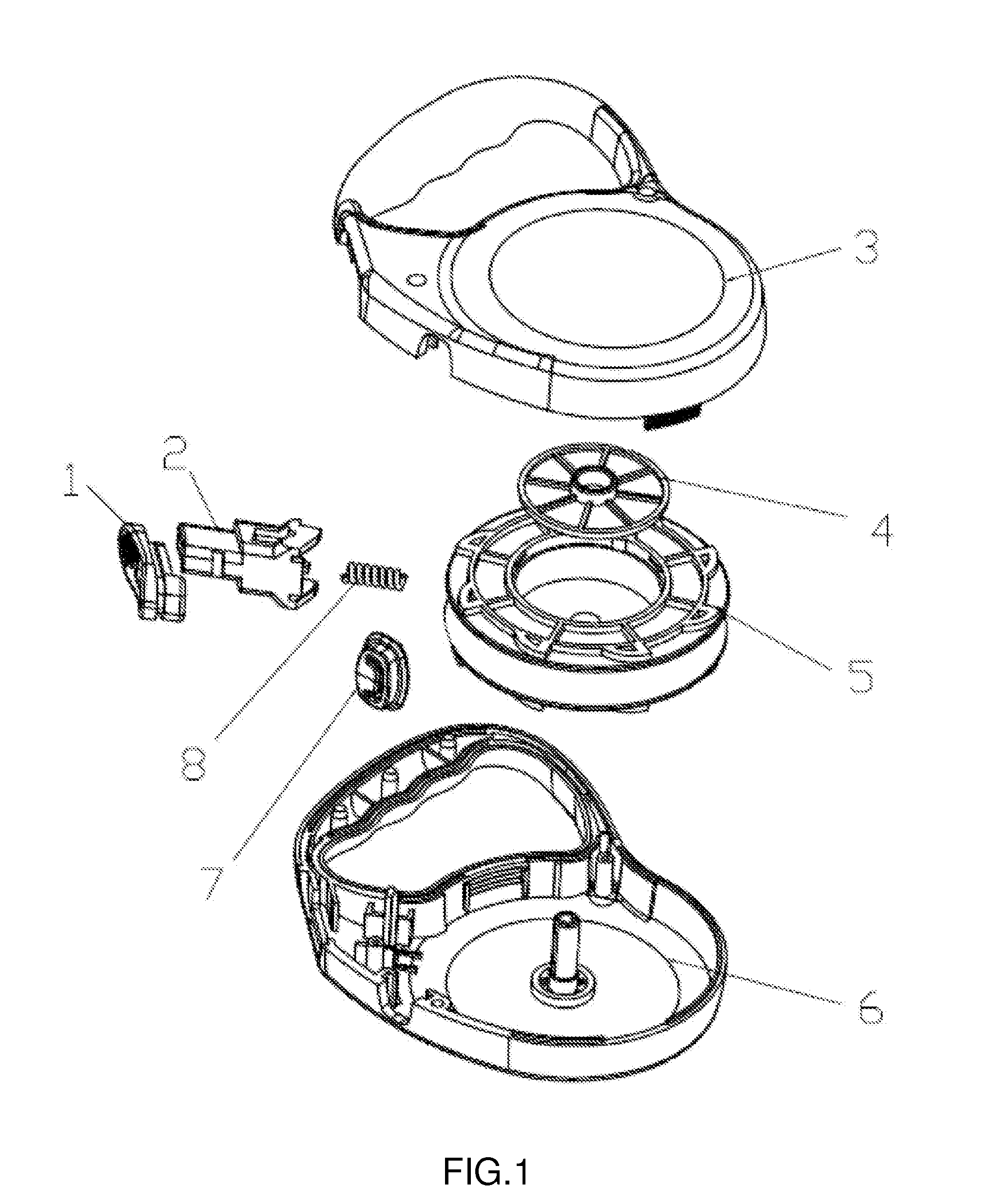
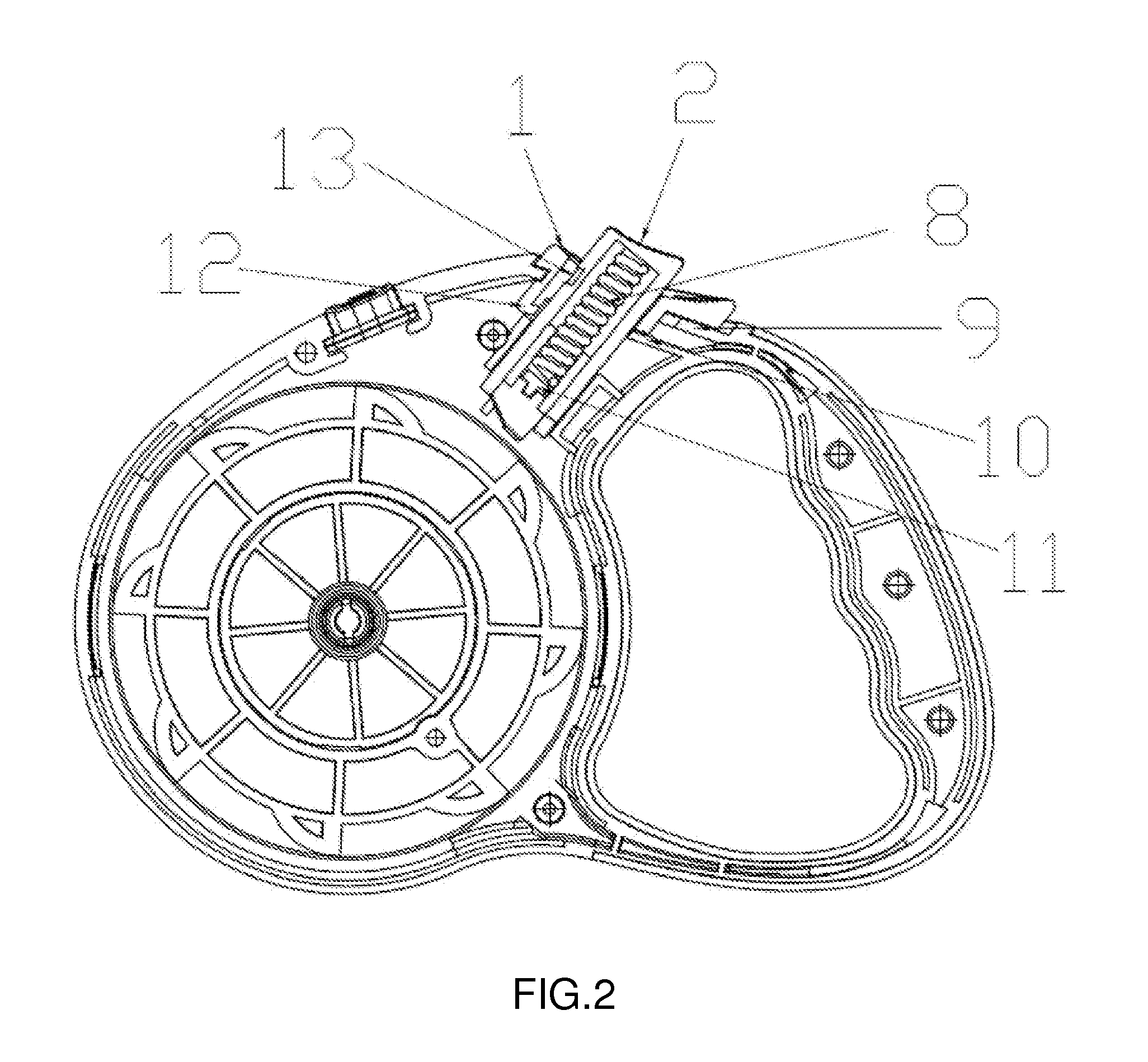
[0017]As shown in FIG. 1 and FIG. 2, a traction switching device, comprising a push-pull button 1, a manual button 2, an upper casing 3, a pulley 5, a pulley cover 4, a lower casing 6 and a reset spring 8, wherein the lower casing 6 is provided with a first slot 9; the push-pull button 1 is imbedded in and sliding back and forth along the first slot 9; the manual button 2 is sleeved on the hole corresponding to the push-pull button 1 and simultaneously is installed at the position corresponding to the lower casing 6 and the upper casing 3; the push-pull button 1 is provided with a hook 12; the manual button 2 is provided with a second slot 13; the reset spring 8 is installed in the manual button 2; one end of the reset spring 8 is fixed on the manual button 2 and the other end is against the lower casing post 11 of the lower casing 6; the lower casing 6 is provided with a clamping point 10 next to the push-pull button 1, to prevent the push-pull button from vibration and looseness d...


PUM


Abstract

A traction switching device, comprising a push-pull button, a manual button, an upper casing, a pulley, a lower casing, a reset spring, wherein the lower casing is provided with a first slot; the push-pull button is imbedded in and sliding back and forth along the first slot; the manual button is sleeved on the hole corresponding to the push-pull button and simultaneously is installed at the position corresponding to the lower casing and the upper casing; the pulley is installed at the central axis of the lower casing; the reset spring is installed in the manual button. The traction switching device is featured with manual, flexible and easy operation, applicable to all domestic pets. By pulling the push-pull button while pressing the manual button, the traction switching device is fully locked; conversely, the traction switching device is unlocked by the push-pull button.

Description

BACKGROUND OF THE INVENTION[0001]The utility model relates to traction devices, particularly relating to a traction switching device.[0002]As more and more people love raising pets, tractions have been increasingly used and accepted. Different tractions are used in different places, thus a wide variety of tractions are required to meet the market demand. Pulley switch is one of the key devices for the traction, directly influencing its operation performance. The pulley switch is required to have dual braking function - interrupting and locking pulley rotation. Currently, the existing traction pulley braking switch is featured with complex and non-portable structure as well as inconvenient operation, which can not meet the existing market demand.[0003]With application number of 201020231891.9, a dog leash pulley rotating and braking switching device, comprising a casing and a cover, wherein the casing is in-built with a pulley; characterized in that, the casing is provided with a swi...

Claims


Application Information

Patent Timeline
Patent Type & Authority Applications(United States)
IPC IPC(8): A01K27/00B65H75/30
CPCB65H75/30A01K27/004B65H75/4431B65H2701/35
Inventor SHI, FUYOU
Owner SHI FUYOU
Why Eureka
Try Eureka