Timepiece movement comprising a date correction mechanism

a date correction and timepiece technology, applied in the field of mechanical horology, can solve the problems of limiting the choice of decorative designs of the watch, affecting the accuracy of the date driver arm,

Active Publication Date: 2017-03-16
ETA SA MFG HORLOGERE SUISSE
View PDF3 Cites 3 Cited by
  • Summary
  • Abstract
  • Description
  • Claims
  • Application Information

AI Technical Summary

Benefits of technology

[0006]More precisely, an object of the invention is to provide a timepiece movement that allows a rapid correction of the date by the control stem and requires no opening in the case relating to the pushbutton that was previously necessary to conduct this function.
[0007]It is also an object of the invention to provide a timepiece movement that allows a unidirectional correction of the date by the control stem.

Problems solved by technology

However, this configuration requires provision of an opening in the case for the pushbutton to pass through, and this has the disadvantage of weakening the seal of the watch and limiting the choice in decorative designs of the watch.
There is a risk of breaking the date driver arm if the user performs a correction of the date at around midnight.

Method used


Image

  • Timepiece movement comprising a date correction mechanism
  • Timepiece movement comprising a date correction mechanism
  • Timepiece movement comprising a date correction mechanism

Examples


Embodiment Construction

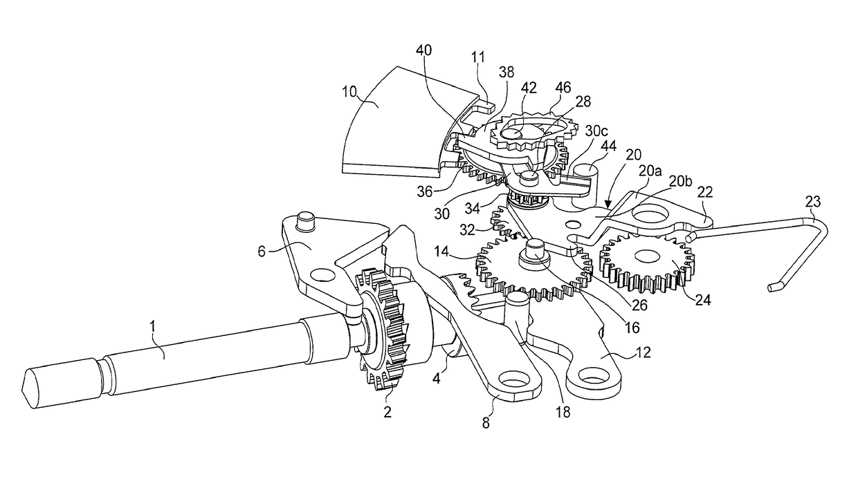
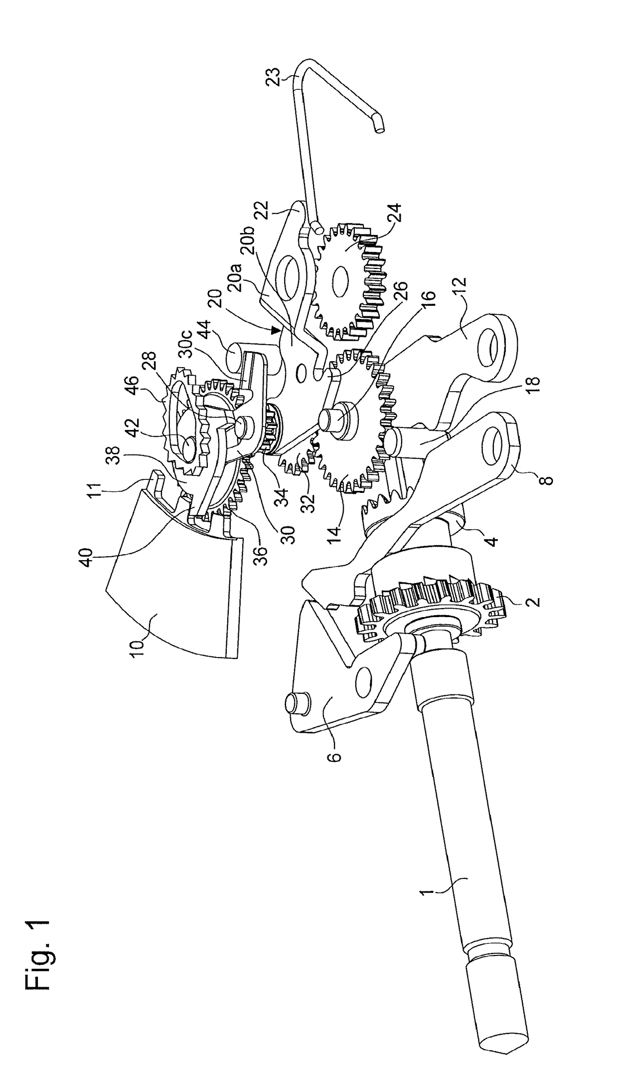
[0031]FIG. 1 shows a part of a timepiece movement comprising in particular a control stem 1, a winding mechanism, a date display mechanism and a time display mechanism.

[0032]Classically, the control stem 1 or winder stem is operable from outside the case of the movement and is movable both rotatably and in translation to occupy its different positions. A winding pinion 2 and a sliding pinion 4 are also provided, the positioning of the sliding pinion 4 being assured by a pull-out piece 6 and a lever 8.

[0033]Classically, the winding pinion 2 meshes with the winding mechanism (not shown) to conduct the manual winding of the movement when the control stem occupies its winding position (in general, the position where it is not pulled out) and when the sliding pinion 4 cooperates with the winding pinion 2, as shown in FIG. 3.

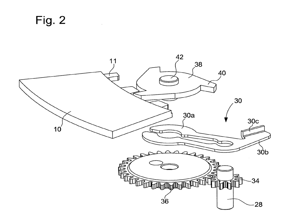
[0034]The date display mechanism classically comprises a day date disc or ring 10 having an inside toothing 11 that can be actuated by a day date mechanism.

[0035]The ...


PUM


Abstract

A timepiece movement including a first lever bearing a first drive wheel, a second lever bearing a second wheel for time setting, and a third lever bearing a date correction mechanism. The third lever is mounted to pivot on the second lever and arranged to move between a meshing position, in which the date correction mechanism cooperates with the date display mechanism, and a retraction position, in which the date correction mechanism is disconnected from the date display mechanism. The first and second levers are arranged to occupy at least one date correction position, in which the first drive wheel is kinematically connected to the date correction mechanism and is not kinematically connected to the second wheel for time setting, and a time setting position, in which the first drive wheel is kinematically connected to the second wheel for time setting and is not kinematically connected to the date correction mechanism, wherein the position of the second lever is modified by cooperation between the first lever and the second lever.

Description

[0001]This application claims priority from European Patent application 15185349.6 of Sep. 15, 2015, the entire disclosure of which is hereby incorporated herein by reference.FIELD OF THE INVENTION[0002]The invention relates to the field of mechanical horology. More particularly, it relates to a timepiece movement comprising a control stem, a winding mechanism for winding the movement, a date display mechanism and a time display mechanism.BACKGROUND OF THE INVENTION[0003]Numerous mechanical watches classically comprise a control stem arranged at 3 o'clock and capable of occupying two positions, i.e. a manual winding position and a time setting position. These watches can also comprise a data display mechanism. A rapid correction of the date is performed by means of a pushbutton provided on the watch case at a different position from the control stem, e.g. at 10 o'clock. However, this configuration requires provision of an opening in the case for the pushbutton to pass through, and t...

Claims


Application Information

Patent Timeline
Patent Type & Authority Applications(United States)
IPC IPC(8): G04B3/00
CPCG04B3/003G04B19/25
Inventor PHILIPPON, DAVIDMERTENAT, OLIVIERWYSSBROD, BAPTIST
Owner ETA SA MFG HORLOGERE SUISSE
Why Eureka
Try Eureka