Stretchable circuit board and method for manufacturing stretchable circuit board

a technology of stretchable circuit boards and stretchable components, which is applied in the direction of circuit bendability/stretchability, printed circuit manufacturing, printed circuit aspects, etc., can solve the problems of not taking handleability into consideration, stretchable circuit boards, etc., and achieve excellent stretchability and handleability , the effect of high reliability of electrical properties

Active Publication Date: 2017-04-06
NIPPON MEKTRON LTD
View PDF1 Cites 13 Cited by
  • Summary
  • Abstract
  • Description
  • Claims
  • Application Information

AI Technical Summary

Benefits of technology

[0008]The present invention has been made in view of the problems described above, and provides a stretchable circuit board that has excellent stretchability and handleability while exhibiting highly reliable electrical properties, and a method for manufacturing the stretchable circuit board.
[0019]overlaying the main surface of the reinforcement base with a part of an area where the stretchable wiring portion is formed, in a manner such that the main surface of the reinforcement base faces the main surface of the stretchable base, and joining together a part of the stretchable wiring portion and a part of the draw-out wiring portion to cause these parts to be electrically continuous with each other.

Problems solved by technology

However, the stretchable circuit board described in Japanese Patent Application Laid-open No. 2014-236103 or Japanese Patent Application Laid-open No. 2014-162124 does not take handleability into consideration.

Method used


Image

  • Stretchable circuit board and method for manufacturing stretchable circuit board
  • Stretchable circuit board and method for manufacturing stretchable circuit board
  • Stretchable circuit board and method for manufacturing stretchable circuit board

Examples


first exemplary embodiment

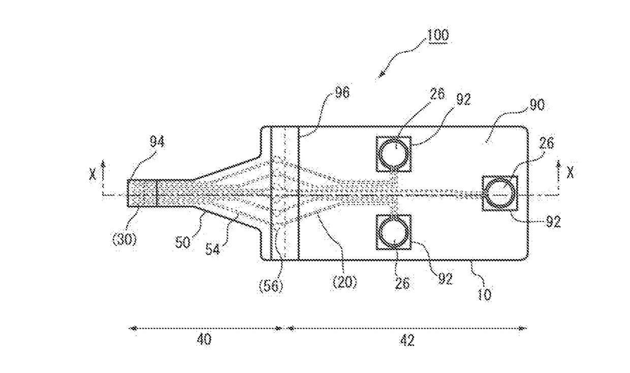
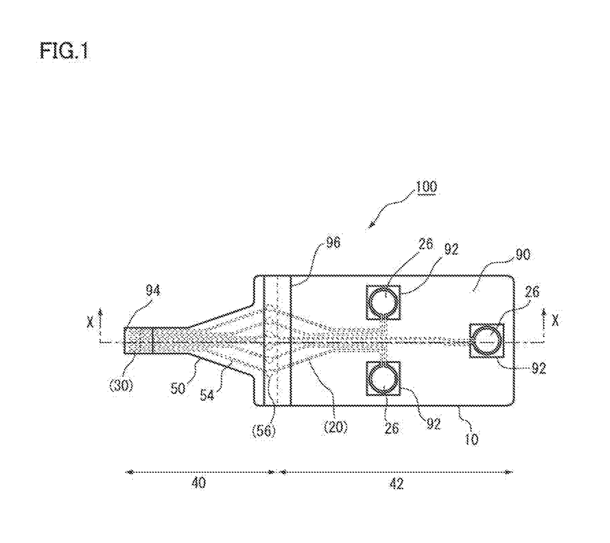
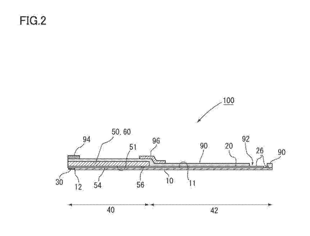
[0038]FIG. 1 is a plan view illustrating a stretchable circuit board 100 according to a first exemplary embodiment of the present invention. FIG. 2 is a sectional view taken along the line X-X in FIG. 1. First, the outline of the first exemplary embodiment will be described. For the purpose of convenience, in some cases in the following description, the bottom side in FIG. 2 is called a lower surface side, and the top side in FIG. 2 and the side toward a reader who is looking at FIG. 1 are called an upper surface side. However, these directions are defined for the purpose of convenience with the aim of illustrating relative positional relationships of constituent elements, and do not necessarily match the top or bottom in the gravity direction.

[0039]The stretchable circuit board 100 includes a stretchable base 10, a stretchable wiring portion 20, a reinforcement base 50 having in-plane rigidity higher than that of the stretchable base 10, and a draw-out wiring portion 54. The stretc...

second exemplary embodiment

Second Modification of Second Exemplary Embodiment

[0178]In the second exemplary embodiment described above, no specific description has been made of the protection layer 90. The stretchable circuit board 200 according to the second exemplary embodiment described above may further include a protection layer 90 that covers a surface on which the stretchable wiring portion20, which is formed on the main surface 11a of the stretchable base 10a, is formed. In addition, the protection layer 90 may not only be provided on the surface on which the stretchable wiring portion 20 is formed, but also be provided so as to cover at least a part of the upper surface (a surface located opposite to the main surface 11b) of the stretchable base 10b.

[0179]FIG. 14 is a sectional view taken along the line W-W in FIG. 8 on the assumption that FIG. 8 is a plan view illustrating a stretchable circuit board 400 according to the second modification of the second exemplary embodiment. However, for the purpos...


PUM


Abstract

A stretchable circuit board includes a stretchable base, a stretchable wiring portion, a reinforcement base having in-plane rigidity higher than that of the stretchable base 10, and a draw-out wiring portion. The stretchable wiring portion having stretchability is formed on a main surface located on at least one side of the stretchable base. The draw-out wiring portion is formed at least on a main surface that is one side of the reinforcement base. The main surface of the reinforcement base is overlaid with a part of an area where the stretchable wiring portion is formed, in which the main surface faces the main surface of the stretchable base. A part of the stretchable wiring portion and a part of the draw-out wiring portion are joined together, and they are electrically continuous.

Description

CROSS-REFERENCE TO RELATED APPLICATIONS[0001]This application claims the benefit of Japanese Patent Applications No.2015-195684 filed on Oct. 1, 2015 and No.2015-256652 filed on Dec. 28, 2015 in the Japanese Patent Office, the disclosures of which are herein incorporated in its entirety by reference.BACKGROUND OF THE INVENTION[0002]The present invention relates to stretchable circuit boards including a stretchable base and a stretchable wiring portion, and methods for manufacturing the same.[0003]In the wearable device market and the medical device market, biological sensors and biological information monitors have received much attention in recent years. For example, the sports industry has been making an effort to quantify body movements of competitors in a highly precise manner in order to improve competitors' physical ability or skills. In such a case, wearable biological sensors that sense movement of a living body are used in some occasions. In addition, the medical industry h...

Claims


Application Information

Patent Timeline
Patent Type & Authority Applications(United States)
IPC IPC(8): H05K1/02H05K1/03H05K1/09H05K3/36
CPCH05K1/0283H05K1/092H05K1/0393H05K3/365H05K1/118H05K2201/2009
Inventor IWASE, MASAYUKI
Owner NIPPON MEKTRON LTD
Why Eureka
Try Eureka