Wheelchair

a technology for wheelchairs and wheelchairs, applied in wheelchairs/patients, medical transportation, ambulance services, etc., can solve the problems of poor rigidity, insufficient robustness, and inability to fold, and achieve the effect of facilitating folding operation, excellent form stability, and stably rotating

Active Publication Date: 2019-08-01
YOSIZUKA SEIKI CO LTD
View PDF1 Cites 1 Cited by
  • Summary
  • Abstract
  • Description
  • Claims
  • Application Information

AI Technical Summary

Benefits of technology

[0026]The above arrangement achieves the following effects in addition to the above effects of the invention.[0027](1) When the connection unit in use is the foldable connection unit, the wheelchair can be folded in the width direction as needed. The wheelchair thus exhibits excellent space-saving properties and storing properties when not in use. The wheelchair also exhibits excellent transportability and handleability, since the wheelchair can be easily transported by car or the like so that the wheelchair is used at the destination.[0028](2) The shaft support holding the rotary shaft, which is provided to the lower end of each link member of the foldable connection unit, such that the rotary shaft is rotatable is detachably fixed to the corresponding unit fixture. This arrangement allows for easy attachment and detachment of the side frames and the foldable connection unit, so that the foldable connection unit can be easily replaced with another connection unit as needed with excellent efficiency in replacing the connection unit, maintenanceability, and applicability.[0029](3) The shaft support of the foldable connection unit is detachably fixed to the corresponding unit fixture. Thus, after removal of the foldable connection unit, the interior of each side frame has no projection or the like with excellent handleability.[0030](4) The foldable connection unit includes: the pair of link members crossed in an X-shape and rotatably connected by the pivot shaft at the longitudinal center; the shaft support provided to the lower end of each link member and detachably fixed to the corresponding unit fixture; and the seat attachment provided to the upper end of each link member. The rotation of the pair of link members around the pivot shaft and the shaft support causes the right and left side frames to approach each other to be easily folded with excellent foldability.[0031](5) The side frames each include the seat support supporting the seat attachment from below, preventing the right and left side frames from being spaced more than a predetermined distance to reliably support the weight of the user sitting on a seat attached to the seat attachment with excellent form stability.
[0027](1) When the connection unit in use is the foldable connection unit, the wheelchair can be folded in the width direction as needed. The wheelchair thus exhibits excellent space-saving properties and storing properties when not in use. The wheelchair also exhibits excellent transportability and handleability, since the wheelchair can be easily transported by car or the like so that the wheelchair is used at the destination.
[0028](2) The shaft support holding the rotary shaft, which is provided to the lower end of each link member of the foldable connection unit, such that the rotary shaft is rotatable is detachably fixed to the corresponding unit fixture. This arrangement allows for easy attachment and detachment of the side frames and the foldable connection unit, so that the foldable connection unit can be easily replaced with another connection unit as needed with excellent efficiency in replacing the connection unit, maintenanceability, and applicability.
[0029](3) The shaft support of the foldable connection unit is detachably fixed to the corresponding unit fixture. Thus, after removal of the foldable connection unit, the interior of each side frame has no projection or the like with excellent handleability.
[0030](4) The foldable connection unit includes: the pair of link members crossed in an X-shape and rotatably connected by the pivot shaft at the longitudinal center; the shaft support provided to the lower end of each link member and detachably fixed to the corresponding unit fixture; and the seat attachment provided to the upper end of each link member. The rotation of the pair of link members around the pivot shaft and the shaft support causes the right and left side frames to approach each other to be easily folded with excellent foldability.
[0031](5) The side frames each include the seat support supporting the seat attachment from below, preventing the right and left side frames from being spaced more than a predetermined distance to reliably support the weight of the user sitting on a seat attached to the seat attachment with excellent form stability.

Problems solved by technology

In this case, a folding wheelchair is used, since a non-folding wheelchair is difficult to carry.
However, such a wheelchair is not comfortable to sit in due to the poor rigidity and insufficient robustness thereof and thus not suitable for long-time use.(2) Accordingly, while a non-folding wheelchair is favorably used for commuting to school or work, participating in social activities, and the like due to the superior robustness thereof, a folding wheelchair will need to be used if the non-folding wheelchair is difficult to take to a distant travel destination.
This increases the burden on a user and / or a caregiver.

Method used


Image

  • Wheelchair
  • Wheelchair
  • Wheelchair

Examples


first exemplary embodiment

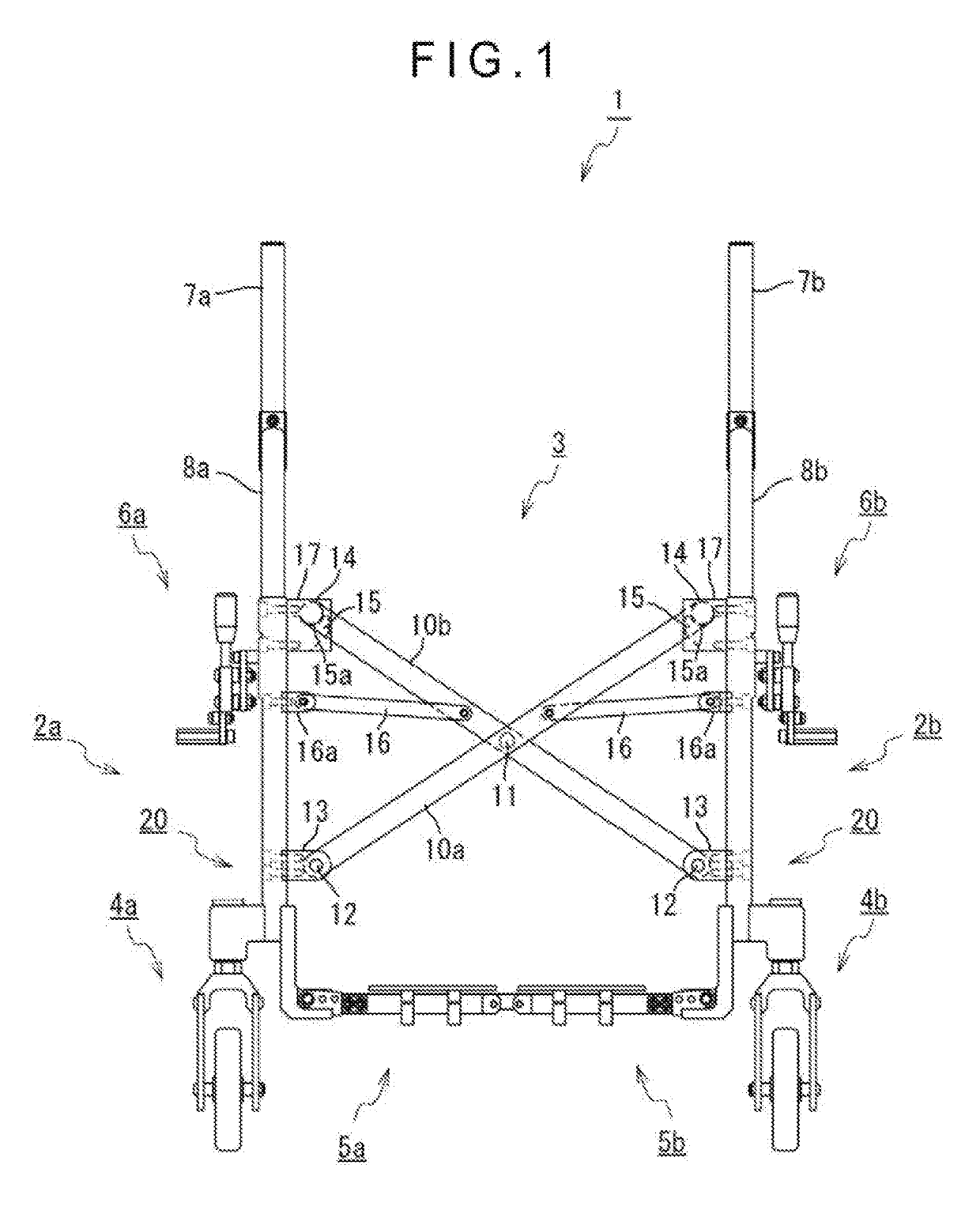
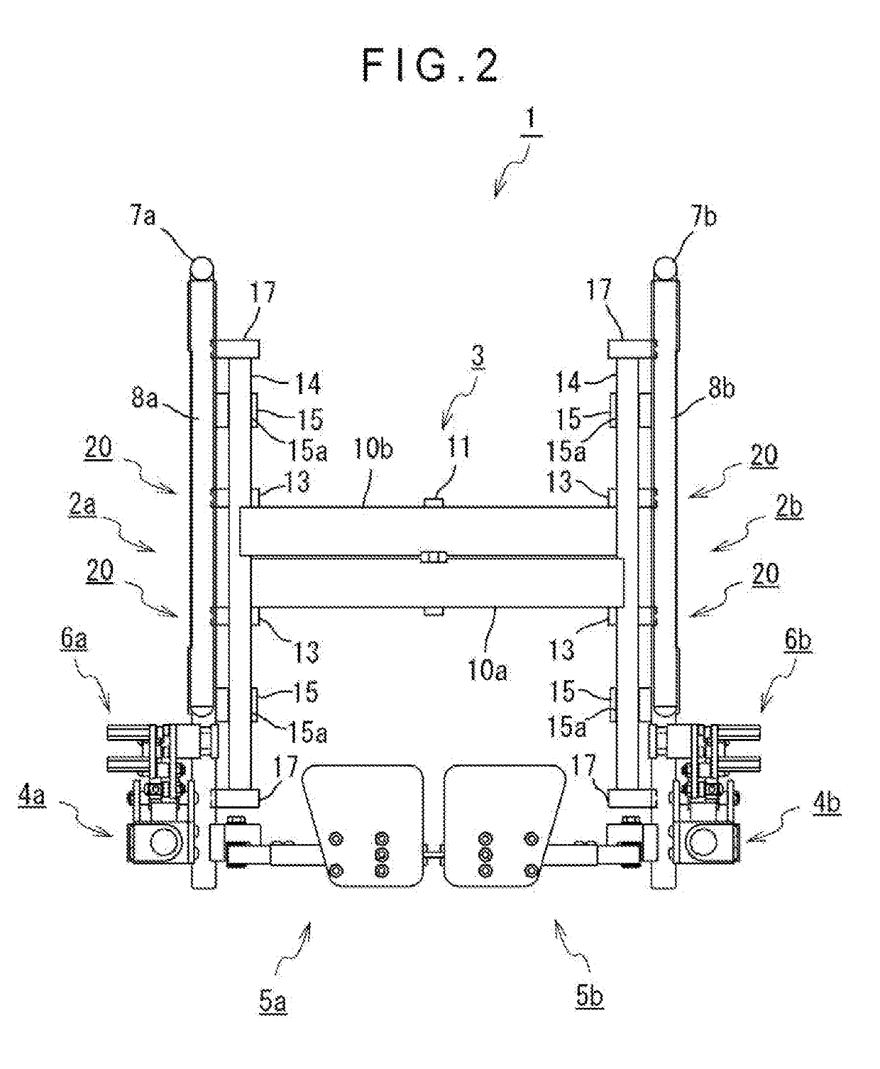
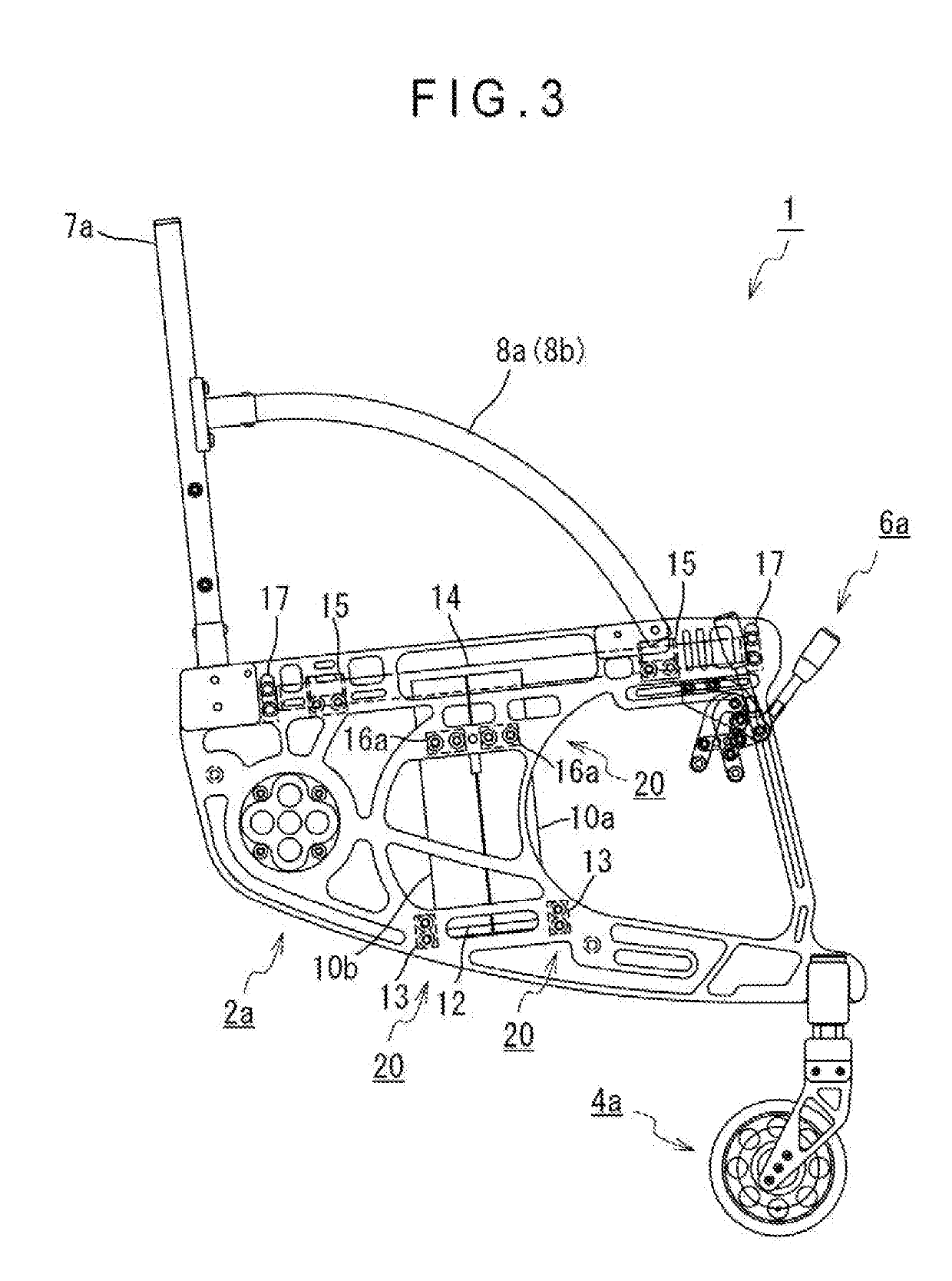
[0063]FIG. 1 is a schematic front view of a relevant part showing a first use form of a wheelchair according to a first exemplary embodiment. FIG. 2 is a schematic plan view of a relevant part showing the first use form of the wheelchair according to the first exemplary embodiment. FIG. 3 is a schematic side view of a relevant part showing the first use form of the wheelchair according to the first exemplary embodiment. It should be noted that right and left wheels, seat, and backrest are not illustrated for the convenience of explanation.

[0064]Referring to FIGS. 1 and 2, a wheelchair 1 according to the first exemplary embodiment includes: right and left side frames 2a, 2b made of a metal such as aluminum and magnesium; a foldable connection unit 3 made of a metal such as aluminum and magnesium and connecting the side frames 2a, 2b to each other such that the side frames 2a, 2b are detachable; front wheels 4a, 4b located at lower front portions of the side frames 2a, 2b, the front w...

second exemplary embodiment

[0097]Next, a wheelchair according to a second exemplary embodiment will be described. A basic configuration of the wheelchair according to the second exemplary embodiment is the same as that of the wheelchair according to the first exemplary embodiment. Accordingly, a description of the common configuration is omitted but different parts will be described below.

[0098]FIG. 9 is a perspective view showing the wheelchair in a first use form according to the second exemplary embodiment with a seat attachment being supported by a seat support. FIG. 10 is a perspective view showing the wheelchair in the first use form according to the second exemplary embodiment with the seat attachment separated from the seat support. FIG. 11 is a perspective view showing the wheelchair in the first use form according to the second exemplary embodiment with the seat attachment supported by the seat support as viewed from a different direction.

[0099]FIG. 12 is a perspective view showing a connecting memb...


PUM


Abstract

A wheelchair includes right and left side frames and a connection unit connecting the side frames to each other. The side frames each include a unit fixture for detachably fixing the connection unit. The connection unit is selectable from a foldable connection unit connecting the right and left side frames with a distance therebetween changeable or a non-foldable connection unit connecting the right and left side frames with the distance therebetween kept constant.

Description

[0001]The entire disclosure of Japanese Patent Application No. 2016-200467, filed on Oct. 11, 2016 is expressly incorporated by reference herein.BACKGROUNDTechnical Field[0002]The present invention relates to a wheelchair excellent in applicability and versatility configured to be transformed between a folding wheelchair and a non-folding wheelchair by selecting and replacing parts, such that the wheelchair is usually used as the non-folding wheelchair suitable for, especially, disabled persons who commute to school or work, participate in social activities, and the like, while being transformed into the folding wheelchair as needed so that the wheelchair is compactly folded to be portable, the wheelchair thus eliminating the necessity of preparing two types of wheelchairs such as folding wheelchair and non-folding wheelchair.Related Art[0003]Typical wheelchairs are roughly categorized into two types such as folding wheelchairs and non-folding wheelchairs. For instance, for commutin...

Claims


Application Information

Patent Timeline
Patent Type & Authority Applications(United States)
IPC IPC(8): A61G5/08
CPCA61G5/0866A61G1/02A61G5/08A61G5/0825
Inventor UEDA, HIDENORITAKANABE, MASATSUGU
Owner YOSIZUKA SEIKI CO LTD
Why Eureka
Try Eureka