Displacement mechanism

Active Publication Date: 2017-06-15
NAT TAIPEI UNIV OF TECH
View PDF8 Cites 12 Cited by
  • Summary
  • Abstract
  • Description
  • Claims
  • Application Information

AI Technical Summary

Benefits of technology

[0020]Accordingly, in the displacement mechanism of the present disclosure, the sliding ends of the arm assemblies are respectively slidably connected to the rails, and ends of the parallel linkage assemblies at a side are respectively connected to the swing ends of the arm assemblies in a multidirectional rotating way, so the movable height of the moving platform connected to ends of the parallel linkage assemblies at another side relative to the base is related to the height of the swing ends of the arm assemblies, rather than is limited by the height of the rails. Therefore, by moving the swing ends of the arm assemblies to exceed the height of the rails, the moving platform can be moved to close to the top board of the displacement mechanism, which greatly increase

Problems solved by technology

Furthermore, the mechanism design of the 3D printer 200 cannot

Method used


Image

  • Displacement mechanism
  • Displacement mechanism
  • Displacement mechanism

Examples


Embodiment Construction

[0028]Reference will now be made in detail to the present embodiments of the disclosure, examples of which are illustrated in the accompanying drawings. Wherever possible, the same reference numbers are used in the drawings and the description to refer to the same or like parts.

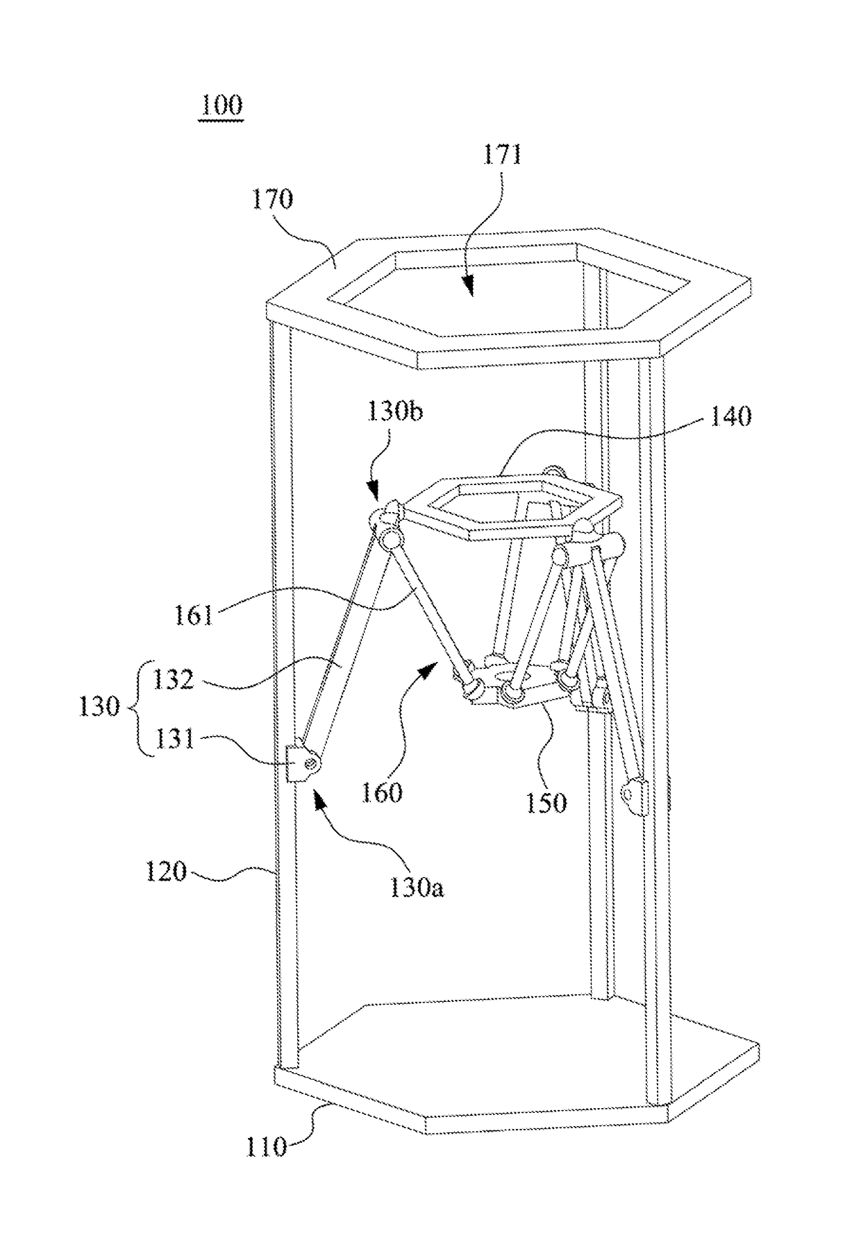
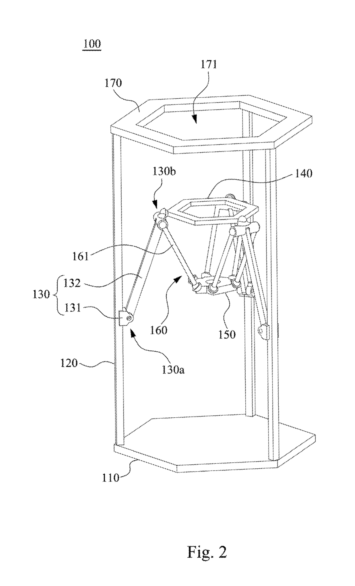
[0029]Reference is made to FIG. 2. FIG. 2 is a perspective view of a displacement mechanism 100 according to some embodiments of the disclosure. As shown in FIG. 2, in some embodiments, the displacement mechanism 100 includes a base 110, three rails 120, three arm assemblies 130, a moving platform 150, three parallel linkage assemblies 160, and a top board 170. The displacement mechanism 100 of the embodiments can be applied in fields of 3D printers, robot mechanisms, electric vehicle carriers, a high-speed displacement mechanisms, and etc. The structures and functions of the foregoing components and the connection relationships among the foregoing components are introduced in detail below.

[0030]As shown in F...


PUM


Abstract

A displacement mechanism includes a base, three rails, three arm assemblies, a moving platform, and three parallel linkage assemblies. The rails stand on the base. Each of the arm assemblies has a first end and a second end. The first ends are slidably connected to the rails, respectively. Each of the arm assemblies is configured to swing in a space among the rails. The moving platform is parallel to the base. Two ends of each of the parallel linkage assemblies are connected to the second end of the corresponding arm assembly and the moving platform in a multidirectional rotating way, respectively. Each of the arm assemblies substantially extends away from the base from the corresponding rail, and each of the parallel linkage assemblies substantially extends toward the base from the second end of the corresponding arm assembly.

Description

RELATED APPLICATIONS[0001]This application claims priority to Taiwan Application Serial Number 104142120, filed Dec. 15, 2015, which is herein incorporated by reference.BACKGROUND[0002]Technical Field[0003]The present disclosure relates to a displacement mechanism, and more particularly, to a delta displacement mechanism.[0004]Description of Related Art[0005]FIG. 1 is a perspective view of a conventional 3D printer 200. As shown in FIG. 1, the 3D printer 200 mainly includes a base 210, a platform 220, three rails 230, three sliders 240, three parallel linkage assemblies 250, and a nozzle 260. The platform 220 is placed on the base 210. The sliders 240 are respectively slidably disposed on the rails 230. Each of the parallel linkage assemblies 250 includes two linkages, and each of the linkages respectively rotatably connected the corresponding slider 240 and the nozzle 260. Hence, by driving the sliders 240 to respectively move on the rails 230, the nozzle 260 can be moved by the pa...

Claims


Application Information

Patent Timeline
IPC IPC(8): F16M13/02B33Y30/00
CPCF16M13/022F16M2200/063B33Y30/00F16M11/046F16M11/121F16M11/18B25J9/0051B25J17/0266
Inventor HWANG, HSIU-YINGHSU, HANG-KUANGLEE, CHIEN-TECHU, YU-CHIH
Owner NAT TAIPEI UNIV OF TECH
Why Eureka
Try Eureka