Electro-optic guest-host liquid crystal variable transmission filter with wide viewing angle

a transmission filter and optical technology, applied in optics, spectacles/goggles, instruments, etc., can solve the problems of unfavorable uniform and asymmetric light intensity perception, unacceptably large viewing angle dependence of transmittance, and inability to achieve high transmittance, so as to reduce contrast ratio, improve viewing angle range, and reduce the effect of contrast ratio

Active Publication Date: 2017-09-28
LC TEC DISPLAY
View PDF3 Cites 41 Cited by
  • Summary
  • Abstract
  • Description
  • Claims
  • Application Information

AI Technical Summary

Benefits of technology

[0006]A preferred embodiment of the disclosed variable transmission filter combines in optical series first and second guest-host liquid crystal devices arranged such that one of them is rotated 180° about its normal axis with respect to the other one of them in a reverse arrangement. The first guest-host device includes first electrode structures having interior surfaces between which is contained liquid crystal material that has liquid crystal directors. The liquid crystal directors have projections lying on the interior surfaces. A polarization state-changing device, such as a half-wave optical retarder, is positioned between the first and second guest-host liquid crystal devices. The reverse arrangement of the liquid crystal directors of the first and second guest-host liquid crystal devices improves the viewing angle range of the variable transmission filter but, as a consequence and without the polarization state changing device, introduces a diminution of contrast ratio. The reason for this diminution of contrast ratio is as follows. Unpolarized light incident on the variable transmission filter can be considered as first and second orthogonally related linear polarization states, the first polarization state and the second polarization state being, respectively, parallel to and perpendicular to the projections of the liquid crystal directors of the first guest-host liquid crystal device. In the absence of compensation there is no appreciable change in transmittance of light of the second polarization state propagating through the variable transmission filter in response to electric fields applied to the first and second guest-host liquid crystal devices and the contrast ratio of the variable transmission filter will always be less than 2. The diminution of contrast ratio caused by the reverse arrangement can be compensated for by positioning the polarization state-changing device between the first and second guest-host liquid crystal devices to introduce changes in the polarization states of light exiting the first guest-host liquid crystal device such that transmittance of light in the first polarization state and in the second polarization state incident on the first guest-host liquid crystal device responds to, respectively, an electric field applied to the first guest-host liquid crystal device and an electric field applied to the second guest-host liquid crystal device. The polarization state-changing device counteracts the diminution of contrast ratio resulting from the reverse arrangement of the first and second guest-host liquid crystal devices while maintaining the improved viewing angle range afforded by the reverse arrangement.

Problems solved by technology

Such high transmittance is not possible with traditional liquid crystal variable transmission filters with high-durability input and output polarizers because the high amount of light absorption by these polarizers allows the variable transmission filter to transmit only 18%-20% of unpolarized light.
While it is theoretically possible that this camera iris could transmit 50% of unpolarized light at normal incidence, there is an unacceptably large viewing angle dependence of the transmittance.
Such angular dependent transmittance would result in a non-uniform and asymmetric perception of light intensity, depending upon the viewing angle of the transmitted light reaching the eye of an observer or a light-sensitive area of a recording medium in a camera.

Method used


Image

  • Electro-optic guest-host liquid crystal variable transmission filter with wide viewing angle
  • Electro-optic guest-host liquid crystal variable transmission filter with wide viewing angle
  • Electro-optic guest-host liquid crystal variable transmission filter with wide viewing angle

Examples


Embodiment Construction

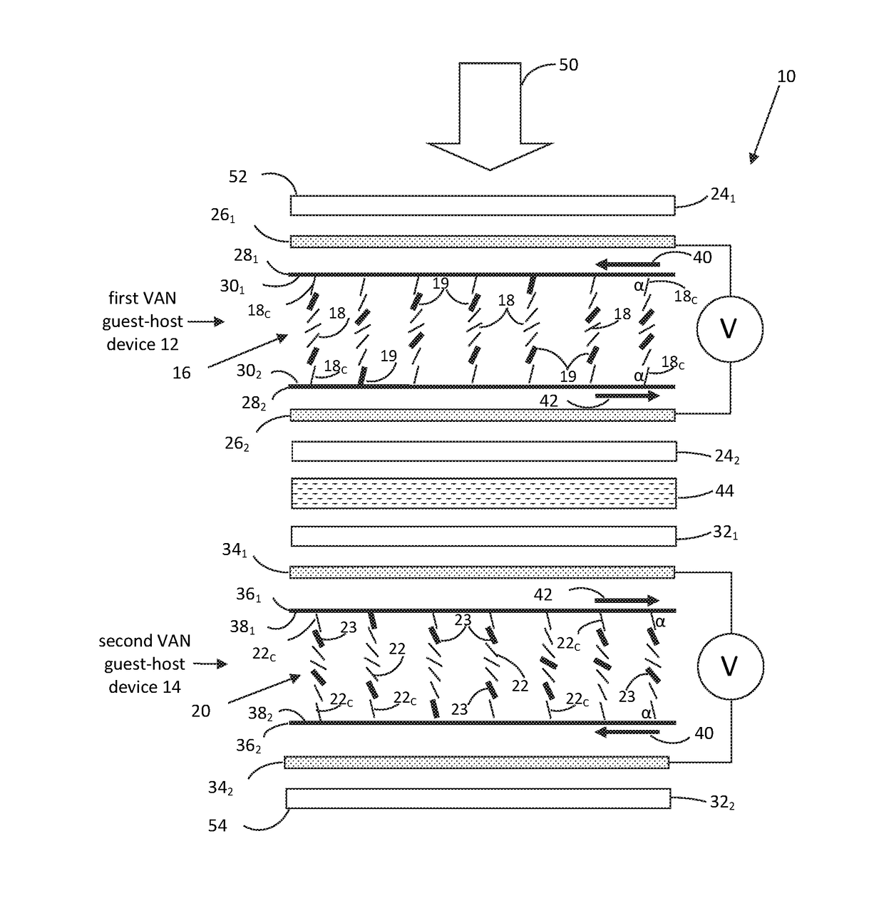
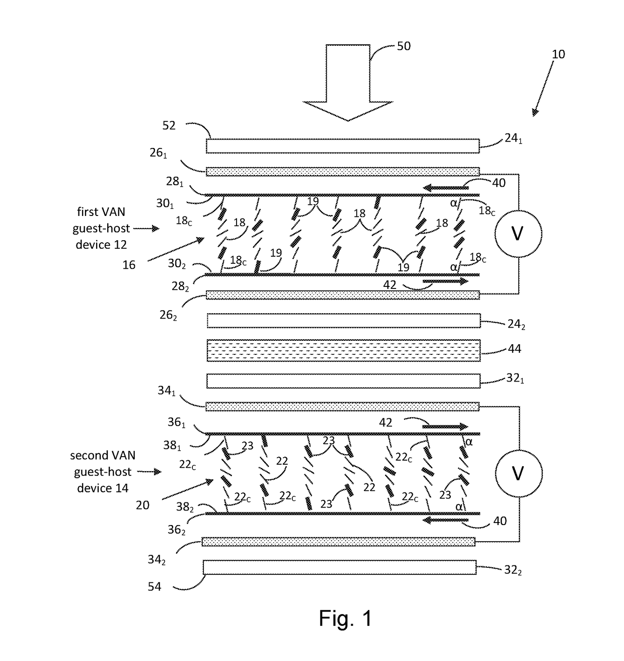
[0063]FIG. 1 is a simplified diagram of a preferred embodiment of the disclosed guest-host liquid crystal variable transmission filter 10, which comprises a first VAN guest-host liquid crystal device 12 and a second VAN guest-host liquid crystal device 14, each of which contains a host liquid crystal having a negative dielectric anisotropy to which a dichroic dye or dye mixture is added. Liquid crystal devices 12 and 14 are of the electrically controlled birefringence (ECB) type, which, for the case of a host liquid crystal with a negative dielectric anisotropy, are also referred to as vertically aligned nematic (VAN) guest-host liquid crystal devices. For simplicity, index matching coatings of each of VAN guest-host liquid crystal devices 12 and 14 are omitted from the diagram. VAN guest-host liquid crystal devices 12 and 14 have, respectively, a director field 16 composed of liquid crystal directors 18 and a director field 20 composed of liquid crystal directors 22. Each of direct...


PUM

PropertyMeasurementUnit
transmittanceaaaaaaaaaa
pretilt anglesaaaaaaaaaa
pretilt angleaaaaaaaaaa

Abstract

A variable transmission filter combines in optical series first and second guest-host liquid crystal devices arranged such that one of them is rotated 180° about its normal axis with respect to the other one. The reverse arrangement of the liquid crystal directors of the first and second guest-host liquid crystal devices improves the viewing angle range of the variable transmission filter but, without compensation, introduces a diminution of contrast ratio. A polarization state-changing device positioned between the first and second guest-host liquid crystal devices changes the polarization states of light exiting the first guest-host_liquid crystal device such that transmittance of light in first and second orthogonal polarization states incident on the first guest-host liquid crystal device responds to electric fields applied to the first and second liquid crystal devices and thereby counteracts the diminution of contrast ratio while maintaining the improved viewing angle range.

Description

RELATED APPLICATION[0001]This application claims benefit of U.S. Patent Application No. 62 / 314,253, filed Mar. 28, 2016.COPYRIGHT NOTICE[0002]© 2017 LC-TEC Displays AB. A portion of the disclosure of this patent document contains material that is subject to copyright protection. The copyright owner has no objection to the facsimile reproduction by anyone of the patent document or the patent disclosure, as it appears in the Patent and Trademark Office patent file or records, but otherwise reserves all copyright rights whatsoever. 37 CFR §1.71(d).TECHNICAL FIELD[0003]This disclosure relates to a guest-host liquid crystal variable transmission filter with a wide viewing angle for an image recording device, such as a camera, or in combination with an image viewing device, such as a background filter for a near-eye display.BACKGROUND INFORMATION[0004]For some applications, it is desirable to have a liquid crystal variable transmission filter that can transmit at least 50% of unpolarized ...

Claims


Application Information

Patent Timeline
Patent Type & Authority Applications(United States)
IPC IPC(8): G02C7/02G02F1/137G02F1/1343G02F1/13363G02F1/1347G02F1/139G02F1/1337
CPCG02C7/022G02F1/1393G02F1/13725G02F1/1337G02F2413/01G02F1/1396G02F1/13475G02F1/13439G02F2001/133638G02F1/13363G02F1/133638
Inventor OSTERMAN, JESPERSCHEFFER, TERRY J.
Owner LC TEC DISPLAY
Why Eureka
Try Eureka