Device for controlling at least one switchable valve

a switchable valve and control device technology, applied in the direction of electrical control, computer control, instruments, etc., can solve the problem of not fully deploying the effect of the switchable valv

Inactive Publication Date: 2017-11-02
ROBERT BOSCH GMBH
View PDF0 Cites 2 Cited by
  • Summary
  • Abstract
  • Description
  • Claims
  • Application Information

AI Technical Summary

Benefits of technology

[0003]An method according to the present invention may have the advantage that the noise effect is maintained even as boundary conditions change, such as the voltage at the valve, the fuel pressure, and the temperature.
[0006]In an improved specific embodiment, the position and / or the length of the brake impulse is specified as a function of further characteristic quantities, such as the temperature, the pressure, and / or the voltage. In this way, a more precise specification of the brake impulse is possible.

Problems solved by technology

If the brake impulse does not take place at the right time and with the right duration, it does not deploy its full effectiveness.

Method used


Image

  • Device for controlling at least one switchable valve
  • Device for controlling at least one switchable valve
  • Device for controlling at least one switchable valve

Examples


Embodiment Construction

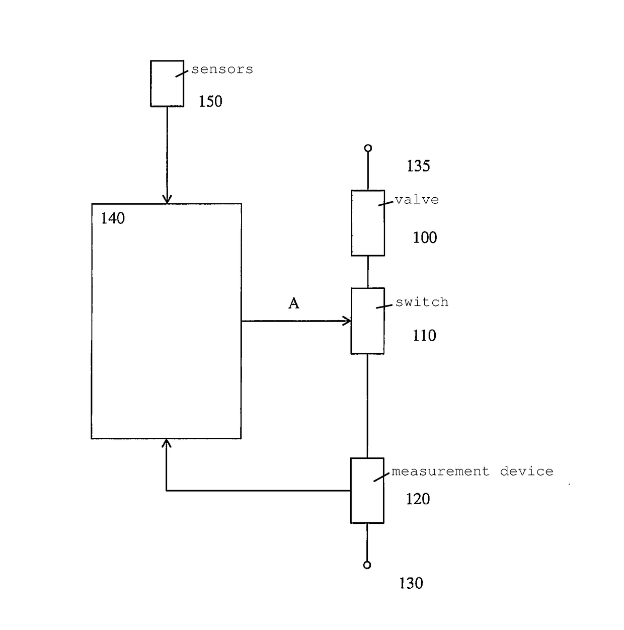
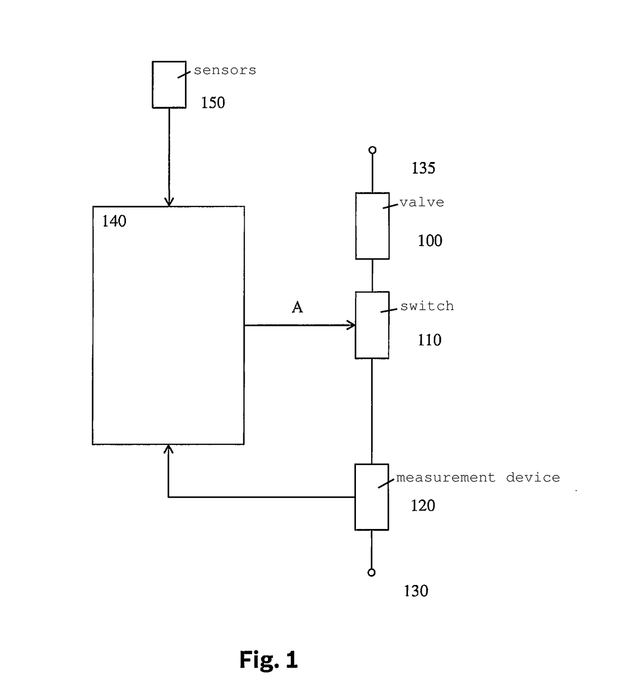
[0018]In FIG. 1, a device is shown for controlling a valve 100. In the depicted specific embodiment, valve 100 is connected in series with a switch 110 and a measurement device 120, between the two terminals 130 and 135 of a power supply. A control device 140 supplies switch 110 with a control signal A. Measurement device 120 supplies control device 140 with a measurement quantity. In addition, sensors 150 are provided that forward sensor signals to control device 140.

[0019]The sequence and the number of elements connected in series are shown only as examples. Measurement device 120, switch 110, and valve 100 can also be configured in a different sequence. In addition, it can be provided that a further switch or other circuit elements are provided.

[0020]Control device 140 calculates, based on various sensor signals and further quantities present in the control device, a control signal A to be supplied to switch 110. A current flows through valve 100 as a function of the position of ...


PUM


Abstract

A method for controlling at least one switchable valve, a brake impulse that slows down the valve movement being produced during the controlling of the at least one valve, the position and / or the length of the brake impulse being specified as a function of a switching time of the valve, it being checked whether a characteristic feature occurs that indicates the switching time, and, upon occurrence of the characteristic feature, the position and / or the length of the brake impulse being adapted based on the position of the characteristic feature.

Description

BACKGROUND INFORMATION[0001]German Patent Application No. DE 10 2009 000 132 A1 describes a method for controlling at least one switchable valve. There, in the controlling of the at least one valve a brake impulse is produced that slows down the valve movement. The position and / or the length of the brake impulse are specified as a function of a switching time of the valve. The effect on the switching noise here is essentially a function of the position and the duration of the brake impulse.[0002]If the brake impulse does not take place at the right time and with the right duration, it does not deploy its full effectiveness. In the extreme case, it has no effect. Based on changing conditions and / or aging effects at the valve, the time changes at which the switching time occurs. With this the time also changes at which the brake impulse deploys its full effectiveness.SUMMARY[0003]An method according to the present invention may have the advantage that the noise effect is maintained ev...

Claims


Application Information

Patent Timeline
Patent Type & Authority Applications(United States)
IPC IPC(8): F02D41/24G05B15/02F02D41/26F02M61/10
CPCF02D41/2467F02D41/2438F02D41/26G05B15/02F02D2200/021F02M61/10F02D2200/0602F02D2200/0406F02D2200/0606F02D2200/0618F02D2041/2037F02D2041/2055F02D2041/2058F02D41/20F02D41/34
Inventor RUPP, ANDREASREINEKE, BASTIANSTEINBRECHER, CHRISTIANHAMEDOVIC, HARISJAHN, STEPHANFISCHER, WOLFGANG
Owner ROBERT BOSCH GMBH
Why Eureka
Try Eureka