Wheel position detecting device and tire pressure detecting apparatus having the same

a technology of position detecting device and tire pressure detecting apparatus, which is applied in the direction of fluid pressure measurement, inflated body pressure measurement, instruments, etc., can solve the problems of inability to specify the wheel position, difficulty in properly counting the tooth number in the low speed region, and difficulty in properly specifying the position of the wheel

Inactive Publication Date: 2017-03-14
DENSO CORP
View PDF9 Cites 1 Cited by
  • Summary
  • Abstract
  • Description
  • Claims
  • Application Information

AI Technical Summary

Benefits of technology

[0013]It is an object of the present disclosure to provide a wheel position detecting device capable of accurately specifying a position of a wheel, and to provide a tire pressure detecting apparatus having the wheel position detecting device.
[0017]In the wheel position detection, the second control unit sets a variation allowance range based on the tooth position at a reception timing of the frame and determines whether the tooth position at a subsequent reception timing of the frame is within the set variation allowance range. When the tooth position of the gear at the subsequent reception timing is not within the variation allowance range, the second control unit excludes the wheel corresponding to the gear from a candidate wheel to which the transmitter is integrated until one wheel remains, and registers a remaining wheel as the wheel to which the transmitter is integrated. The second control unit prevents the wheel position detection when a wheel speed detected based on a detection signal of the wheel speed sensor is equal to or lower than a predetermined threshold, and performs the wheel position detection only when the wheel speed is higher than the predetermined threshold.
[0018]In the wheel position detecting device described above, the wheel position detection is not performed in a low speed region where the wheel speed is equal to or lower than the predetermined threshold. Therefore, it is less likely that the wheel position detection will be performed based on an inaccurate tooth position. Namely, since the wheel position detection is performed only when the wheel speed is higher than the predetermined threshold, the wheel position is accurately specified.

Problems solved by technology

However, the wheel speed pulse outputted from the wheel speed sensor is likely to largely vary in a low speed region, and it is difficult to properly count the tooth number in the low speed region.
Therefore, although the wheel is actually rotating, if the tooth number calculated and the rotational position of the wheel detected based on the acceleration detection signal of the acceleration sensor are largely varied relative to each other, it is difficult to properly specify the position of the wheel.
Therefore, the wheel position cannot be specified until the certain amount of data is made.
Therefore, it takes time to specify the wheel position.

Method used


Image

  • Wheel position detecting device and tire pressure detecting apparatus having the same
  • Wheel position detecting device and tire pressure detecting apparatus having the same
  • Wheel position detecting device and tire pressure detecting apparatus having the same

Examples


first embodiment

[0036]A first embodiment will be described with reference to FIGS. 1 to 8D.

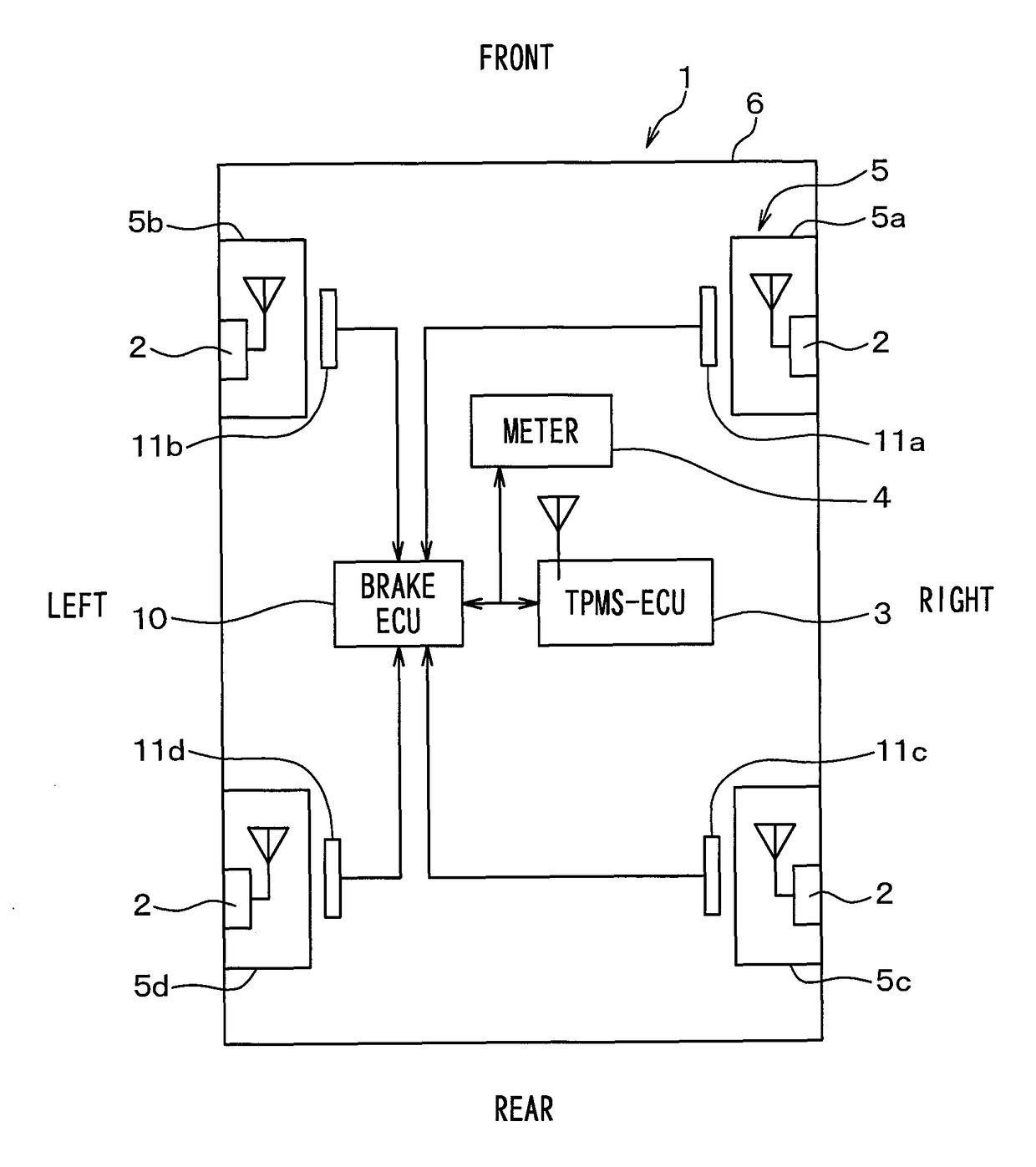
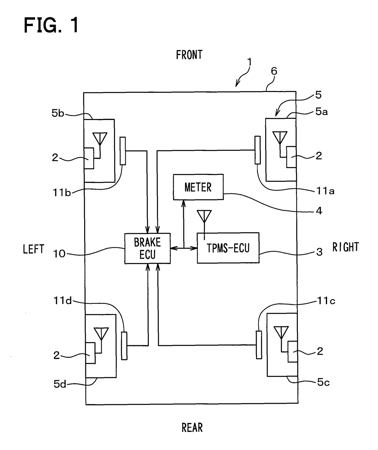
[0037]FIG. 1 is a schematic diagram illustrating an overall structure of a wheel position detecting device and an overall structure of a tire pressure detecting apparatus in a vehicle 1. In FIG. 1, an upward direction corresponds to a frontward direction of the vehicle 1, and a downward direction corresponds to a rearward direction of the vehicle 1. The tire pressure detecting apparatus according to the present embodiment will be described with reference to FIG. 1.

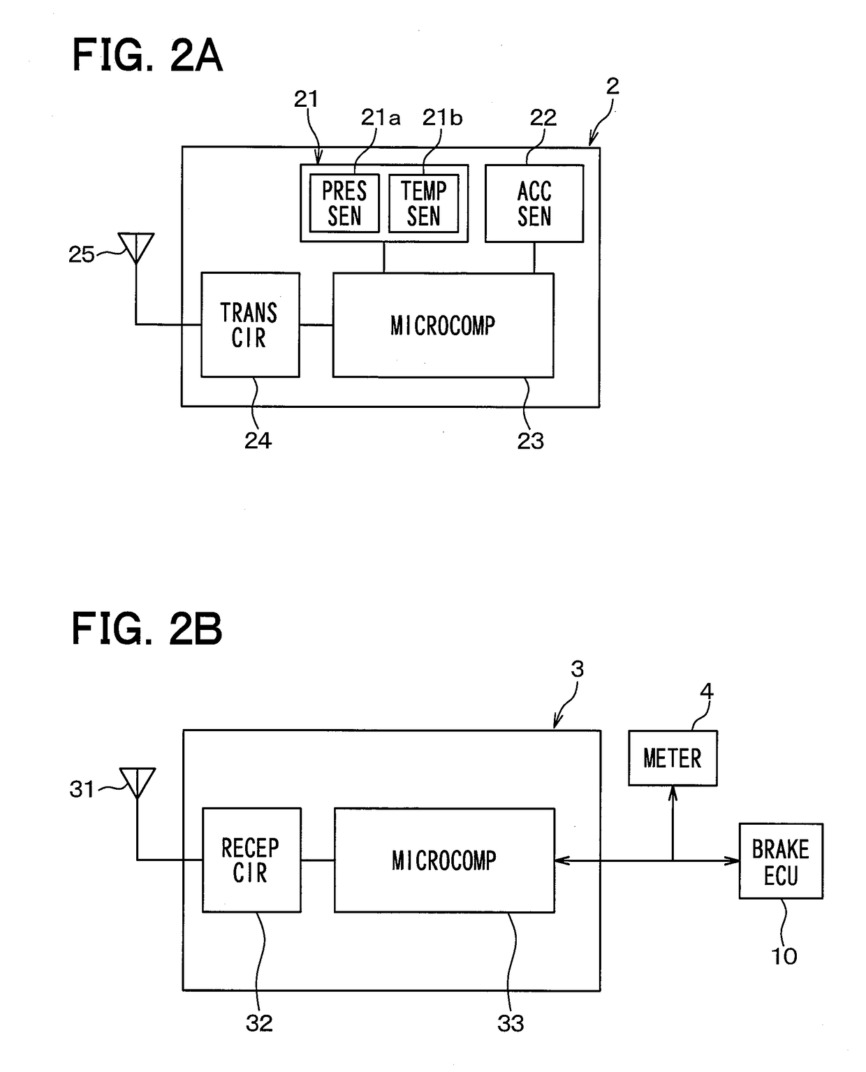
[0038]The tire pressure detecting apparatus is equipped to the vehicle 1. The tire pressure detecting apparatus includes a transmitter 2, a tire pressure monitoring system electronic control unit (hereinafter referred to as the TPMS-ECU) 3, and a meter 4. The TPMS-ECU 3 serves as a receiver.

[0039]The wheel position detecting device uses the transmitter 2 and the TPMS-ECU 3, which are included in the tire pressure detecting apparatus. The wheel posit...

second embodiment

[0125]A second embodiment of the present disclosure will be hereinafter described. In the second embodiment, a way of transmitting the frame from the transmitter 2 is different from that of the first embodiment. Other features are the same as the first embodiment. Therefore, the feature different from the first embodiment will be mainly described.

[0126]In the first embodiment, the transmitter 2 transmits the frame each time the acceleration sensor 22 is at a certain angular position. That is, the transmission angular position of the transmitter 2 is fixed. In the present embodiment, on the other hand, the transmission angular position is changed each time that the vehicle 1 stops.

[0127]In a case where the transmission angular position of the transmitter 2 is fixed, if the transmission angular position coincides with a position where the frame is less likely to reach the TPMS-ECU 3, such as a Null, it will be difficult that the TPMS-ECU 3 receives the frame every time the frame is tr...


PUM

PropertyMeasurementUnit
speedaaaaaaaaaa
reception angleaaaaaaaaaa

Abstract

In a wheel position detecting device, a receiver acquires gear information indicating a tooth position of a gear rotating in association with a corresponding wheel at a predetermined interval. In a wheel position detection, the receiver sets a variation allowance range based on the tooth position at a reception timing of a frame transmitted from a transmitter integrated to each wheel. When the tooth position of the gear at a subsequent reception timing of the frame is not within the variation allowance range, the receiver excludes the wheel corresponding to the gear from a candidate wheel. The receiver registers the wheel remaining last as the wheel to which the transmitter is integrated. The receiver performs the wheel position detection only when a wheel speed is higher than a predetermined threshold, so that the wheel position detection is performed based on an accurate tooth position.

Description

CROSS REFERENCE TO RELATED APPLICATIONS[0001]This application is a U.S. National Phase Application under 35 U.S.C. 371 of International Application No. PCT / JP2013 / 051942 filed on Jan. 23, 2013 and published in English as WO 2013 / 111910 A1 on Aug. 1, 2013. This application is based on Japanese Patent Application No. 2012-15133 filed on Jan. 27, 2012. The entire disclosures of all of the above applications are incorporated herein by reference.TECHNICAL FIELD[0002]The present disclosure relates to a wheel position detecting device that detects a position of a subject wheel in a vehicle, and a tire pressure detecting apparatus having the wheel position detecting device.BACKGROUND ART[0003]For example, a wheel position detecting device automatically detects a position of a subject wheel in a vehicle. Also, it has been known to use a wheel position detecting device in a tire pressure detecting apparatus for detecting a tire pressure of a wheel. As an example of the tire pressure detecting...

Claims


Application Information

Patent Timeline
Patent Type & Authority Patents(United States)
IPC IPC(8): B60C23/04G01P3/44G01L17/00G01P15/00
CPCB60C23/0489B60C23/0416G01L17/00G01P3/44G01P15/003
Inventor OKADA, NORIAKIWATABE, NOBUYAMORI, MASASHISEKIZAWA, TAKATOSHI
Owner DENSO CORP
Why Eureka
Try Eureka