Specific phase position detection circuit and method of the same

a phase position detection and phase position technology, applied in the direction of amplitude demodulation, process and machine control, instruments, etc., can solve the problems of failure to apply the required voltage to the discharge lamp, difficulty in identifying peak positions, and difficulty in retaining the discharge lamp. achieve the effect of high accuracy and stably keeping

Inactive Publication Date: 2009-07-28
SEIKO EPSON CORP
View PDF10 Cites 2 Cited by
  • Summary
  • Abstract
  • Description
  • Claims
  • Application Information

AI Technical Summary

Benefits of technology

[0023]The object of the invention is thus to eliminate the drawbacks of the prior art technique and to provide a technique of accurately specifying peak positions even in an analog signal with varying amplitude.

Problems solved by technology

Application of the voltage having the fixed frequency to the resonant circuit under the condition of the varying resonant frequency causes failed application of the required voltage to the discharge lamp and does not keep the discharge lamp on.
Identification of the peak positions, however, has much difficulty, and the phase comparison may be performed according to the following procedure.
The inaccurate detection of the phase difference interferes with precise adjustment of the frequency of the applied voltage and prevents stable lighting of the discharge lamp.
This problem is not characteristic of the phase comparison but also arises in detection of phase detection points as peak positions of an analog signal representing a variation in electric current or voltage in the resonant circuit.
Detection of such phase detection points as the peak positions may accordingly have an error out of a preset allowable range.
Such problems are not restricted to the analog signals in the resonant circuit but may arise in detection of peak positions in any analog signal having varying amplitude.

Method used


Image

  • Specific phase position detection circuit and method of the same
  • Specific phase position detection circuit and method of the same
  • Specific phase position detection circuit and method of the same

Examples


embodiment

A. Embodiment

A1. System Configuration

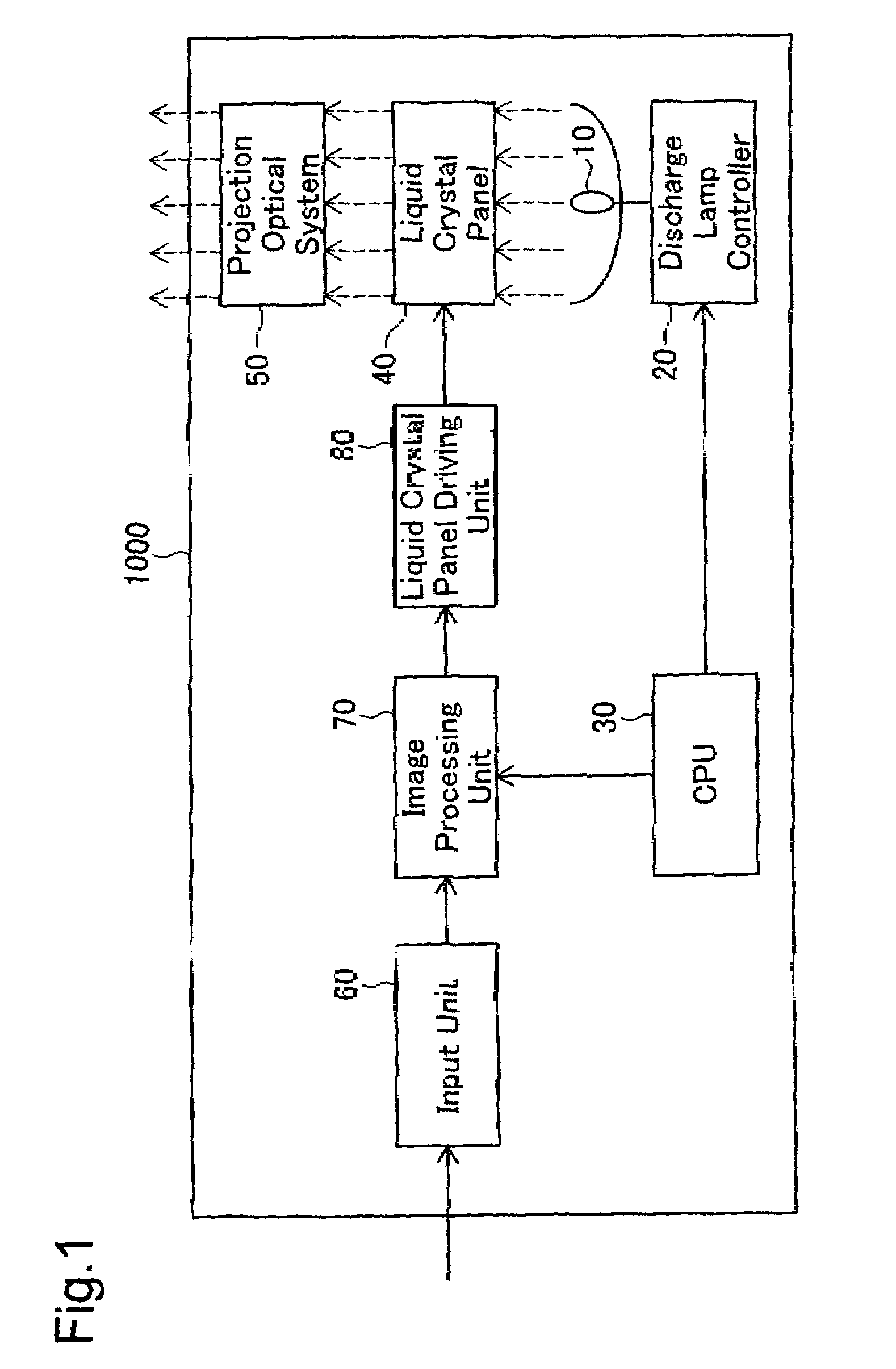
[0057]FIG. 1 schematically illustrates the configuration of a liquid crystal projector 1000 in one embodiment of the invention.

[0058]As illustrated in FIG. 1, the liquid crystal projector 1000 mainly has a discharge lamp 10, a discharge lamp controller 20 that controls lighting of the discharge lamp 10, a CPU 30, a liquid crystal panel 40, a projection optical system 50 including a projection lens, an input unit 60 that receives external analog signals, an image processing unit 70, and a liquid crystal panel driving unit 80 that drives the liquid crystal panel 40.

[0059]The input unit 60 receives analog video signals output from, for example, a video player, a TV set, or a personal computer, and converts the input analog video signals into digital video signals. The image processing unit 70 adjusts the input digital video signals to attain desired image display conditions (including contrast and sharpness) according to an instruction given by the ...

modified example 1

B1. MODIFIED EXAMPLE 1

[0118]In the liquid crystal projector 1000 of the embodiment described above, the voltage corresponding to the sinusoidal signal A1 is applied to the resonant unit 150. The source signal of the applied voltage may not be a sinusoidal wave but may have another waveform. Operation values may be determined corresponding to the respective waveforms and stored in the operation value storage element 340 (see FIG. 3).

[0119]FIG. 7 shows the waveforms of source signals and applied voltage signals and operation values set for the respective waveforms in Modified Example 1.

[0120]A sawtooth wave 1 of FIG. 7 has a peak position shifted by ‘0.8’ from a start position of each cycle that is assumed to be ‘1’. Setting an operation value of ‘0.7’ enables specification of a phase detection point relatively close to the peak position.

[0121]A sawtooth wave 2 has a peak position shifted by ‘0.2’ from a start position of each cycle. A triangular wave and a sinusoidal wave respectivel...

modified example 2

B2. MODIFIED EXAMPLE 2

[0123]The procedure of the embodiment sets the phase detection point of each cycle to the position shifted by ‘0.1’ from the center position of each high-level period of the comparison signal S110 assumed to be ‘1’. The phase detection point is, however, not restricted to the position shifted by ‘0.1’ from the center position. A closer position to the peak position, for example, a position shifted by ‘0.05’ from the center position, may be specified as the phase detection point.

[0124]In this modification, the phase detection point corresponds to the position of 10% before the center position in the specific time length between the start position and the center position in each high-level period of the comparison signal S110. According to the calculation similar to Equation (1) given above, the phase detection point is set at the position of 45% from the rising position in each high-level period of the comparison signal S110, which is assumed to be 100%. The mod...


PUM


Abstract

A specific phase position detection circuit of the invention includes: a measurement unit that detects two time positions where a signal level of an analog signal is matched with a preset threshold value, as a first reference position and a second reference position in each cycle of the analog signal, and measures a time length between the first reference position and the second reference position, as a reference time period; a computation unit that computes a time period at a preset rate to the reference time period measured in each previous cycle, as an additional time period in each current cycle of the analog signal; and a detection unit that detects a time position shifted from the first reference position detected in a current cycle by the additional time period computed by the computation unit, as the specific phase position, and outputs a detection signal representing the detected specific phase position. The positions having the substantially fixed positional relations to the peak positions are detectable as the specific phase positions in the respective cycles of an analog signal. The technique of the invention thus enables accurate specification of the peak positions even in the analog signal with varying amplitude.

Description

BACKGROUND OF THE INVENTION[0001]1. Field of the Invention[0002]The present invention relates to a technique of specifying peak positions of an analog signal. More specifically the invention pertains to a technique of accurately specifying peak positions even in an analog signal with varying amplitude.[0003]2. Description of the Related Art[0004]Recently proposed projectors have a resonant circuit including a coil and a capacitor for lighting control of a discharge lamp. In these projectors, the discharge lamp is connected in parallel with the capacitor of the resonant circuit. The frequency of a voltage applied to the resonant circuit is adjusted to a resonant frequency of the resonant circuit. A required voltage for discharge is then applied to the discharge lamp connected to the resonant circuit to light on the discharge lamp.[0005]One example of such projectors is disclosed in Japanese Patent Laid-Open Gazette No. H05-217682.[0006]In the projector having the resonant circuit for...

Claims


Application Information

Patent Timeline
Patent Type & Authority Patents(United States)
IPC IPC(8): H03D1/00H04L27/06
CPCH04N9/3197H04N9/315
Inventor TAKEUCHI, KESATOSHI
Owner SEIKO EPSON CORP
Why Eureka
Try Eureka