Metal jet x-ray tube

a technology of metal jets and x-ray tubes, applied in the direction of x-ray tube targets, x-ray tube tubes, x-ray tube target materials, etc., can solve the problem of complete deceleration of drawback, and achieve the effect of increasing efficiency and increasing light production efficiency

Active Publication Date: 2017-11-30
SIEMENS HEALTHCARE GMBH
View PDF0 Cites 6 Cited by
  • Summary
  • Abstract
  • Description
  • Claims
  • Application Information

AI Technical Summary

Benefits of technology

[0014]If this decelerating of the electrons is carried out together with an energy recuperation provision, the light production efficiency is increased.
[0015]An additional increase in the efficiency...

Problems solved by technology

In view of the focal spot power deposition, and also in v...

Method used


Image

  • Metal jet x-ray tube
  • Metal jet x-ray tube

Examples


Embodiment Construction

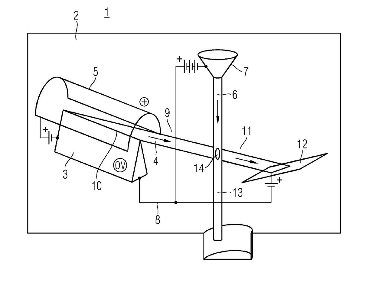
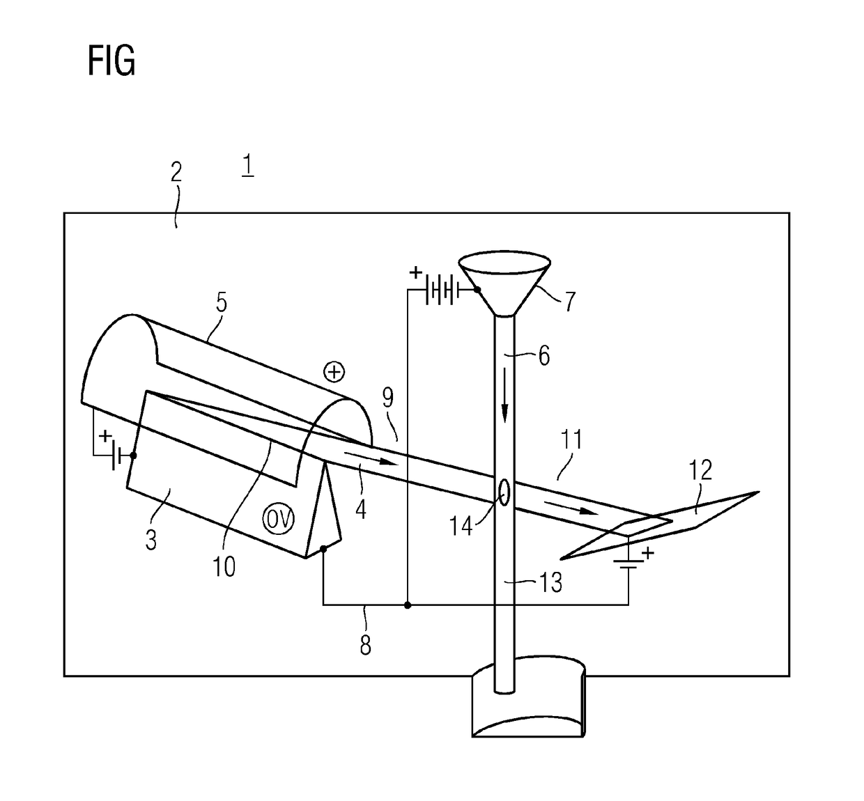
[0018]FIG. 1 depicts a metal jet x-ray tube 1 including a vacuum chamber 2. A cathode component 3 is arranged in the vacuum chamber 2. The cathode component 3 serves to extract an electron beam 4. An extractor 5 for extracting the extraction of the electron beam 4 from the cathode component 3 is provided in the vacuum chamber 2. Also in the vacuum chamber 2 is an anode component 7 formed by a liquid metal jet 6. The liquid metal jet 6 is the target for the emitted electron beam 4 of the cathode component 3. An accelerator 8 is configured for accelerating the electron beam 4 emitted by the cathode component 3 in the direction and with the target of the anode component 7, at least within a vacuum path 9.

[0019]The metal jet 6 is configured as a thin metal jet. The electrons of the electron beam 4 are only partly decelerated by the metal jet 6. The cathode component 3 has a cathode blade 10 such that the cathode component 3 may also be referred to as a blade cathode. The cathode blade 1...


PUM


Abstract

The invention relates to a metal jet x-ray tube which is less affected by the problem of the power density at the point of impact of the electron beam on the anode component than conventional tubes. For this purpose the metal jet x-ray tube has a metal jet (6) as anode component (7), which metal jet is so thin that an electron beam (4) impinging on the metal jet (6) is only partially decelerated by the metal jet. Furthermore a blade cathode is provided as a cathode component (3), which blade cathode comprises a cathode blade (10) directed with a slight inclination downwards in the direction of the liquid metal jet (6) of the anode component (7).

Description

CROSS-REFERENCE TO RELATED APPLICATIONS[0001]The present patent document is a §371 nationalization of PCT Application Serial Number PCT / EP2015 / 080504, filed Dec. 18, 2015, designating the United States, which is hereby incorporated by reference. This patent document also claims the benefit of DE 102014226813.3, filed on Dec. 22, 2014, which is also hereby incorporated by reference.TECHNICAL FIELD[0002]Embodiments relate to a metal jet x-ray.BACKGROUND[0003]In stationary or rotary anode tubes, or metal jet x-ray tubes, there is the problem of a power density at a point of incidence of the electron beam on the anode component. High power losses are generated for given luminous intensities and focal spot luminances. Strong background magnetic fields, for example, caused in conjunction with magnetic resonance imaging scanners cause a problem. It is impossible to focus the electron beam using electrostatic in magnetic fields of such strength.[0004]The problem of maintaining the solid or ...

Claims


Application Information

Patent Timeline
IPC IPC(8): H01J35/06H01J35/12
CPCH01J35/065H01J2235/082H01J2235/062H01J35/12H01J2235/086H01J35/02H01J2235/06
Inventor HEID, OLIVER
Owner SIEMENS HEALTHCARE GMBH
Why Eureka
Try Eureka