Unlock instant, AI-driven research and patent intelligence for your innovation.
Apparatus and method
Active Publication Date: 2017-12-21
SONY CORP
View PDF10 Cites 5 Cited by
Summary
Abstract
Description
Claims
Application Information
AI Technical Summary
This helps you quickly interpret patents by identifying the three key elements:
Problems solved by technology
Method used
Benefits of technology
This patent aims to reduce interference between cells by improving the performance of wireless communication systems. The technical effects of this innovation include better data transmission, increased reliability of wireless networks, and improved overall user experience.
Problems solved by technology
Particularly, directional beams of large-scale MIMO may reach a neighbor cell and cause high received power.
Consequently, large interference may be generated.
Method used
Image
Click on the blue label to locate the original text in one second.
Reading with bidirectional positioning of images and text.
Examples
first example (
(b-1) First Example (Suspension)
[0123]As a first example, the base station 100 (control unit 153) decides suspension of transmission of the signal over the directional beam as the operation. Thereafter, the base station 100 suspends transmission of the signal over the directional beam.
[0124]For example, the base station 100 (control unit 153) decides and executes suspension of transmission of a data signal and / or the reference signal over the directional beam.
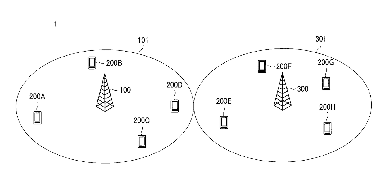
[0125]Accordingly, it is possible to cancel interference of the directional beam in the terminal apparatus 200 connected to the base station 300, for example.
second example (
(b-2) Second Example (Restriction)
[0126]As a second example, the base station 100 (control unit 153) decides restriction on transmission of the signal over the directional beam as the operation. Thereafter, the base station 100 restricts transmission of the signal over the directional beam.
[0128]For example, the restriction includes restricting radio resources in which a data signal is transmitted over the directional beam. That is, the base station 100 (control unit 153) decides restriction on radio resources in which a data signal is transmitted over the directional beam and restricts the radio resources. Consequently, the base station 100 transmits the data signal in the restricted radio resources over the directional beam.
[0129]More specifically, the restriction includes restricting, for example, time resources in which a data signal is transmitted over the directional beam. For example, the time resources are subframes. In this case, the base station 100 transm...
[0134]For example, the base station 100 (control unit 153) decides continuation of transmission of the signal over the directional beam as the operation. Thereafter, the base station 100 continuously transmits the signal over the directional beam.
[0135]Accordingly, it is possible to continue transmission of the signal over the directional beam when it is difficult to suspend and restrict transmission of the signal over the directional beam, for example.
(b-4) Others
[0136]The restriction may include changing the configuration (e.g., radio resources used to transmit a signal (including a period) and / or a sequence of the signal) of a reference signal for channel quality measurement through the directional beam. That is, the base station 100 (control unit 153) may decide changing of the configuration and change the configuration.
[0137]As described above, the directional beam may be a directional beam which obstructs detection of another reference signal ...
PUM
Abstract
[Object] To enable interference of directional beams between cells to further decrease.[Solution] Provided is an apparatus including: an acquisition unit that acquires information about a directional beam that is provided from a neighbor base station of a base station, the directional beam serving as an interference source for a terminal apparatus connected to the neighbor base station among a plurality of directional beams which is able to be formed by the base station; and a control unit that decides an operation of the base station regarding transmission of a signal over the directional beam on the basis of the information.
Description
TECHNICAL FIELD[0001]The present disclosure relates to apparatuses and methods.BACKGROUND ART[0002]In the Third Generation Partnership Project (3GPP), various techniques for improving the capacity of a cellular system are currently studied in order to accommodate explosively increasing traffic. It is also envisaged that the required capacity will become about 1000 times the current capacity in the future. Techniques such as multi-user multi-input multiple-input multiple-output (MU-MIMO), coordinated multipoint (CoMP), and the like could increase the capacity of a cellular system by a factor of as low as less than ten. Therefore, there is a demand for an innovative technique.[0003]For example, as a technique for significantly increasing the capacity of a cellular system, a base station may perform beamforming using a directional antenna including a large number of antenna elements (e.g., about 100 antenna elements). Such a technique is a kind of technique called large-scale MIMO or m...
Claims
Application Information
Patent Timeline
Application Date:The date an application was filed.
Publication Date:The date a patent or application was officially published.
First Publication Date:The earliest publication date of a patent with the same application number.
Issue Date:Publication date of the patent grant document.
PCT Entry Date:The Entry date of PCT National Phase.
Estimated Expiry Date:The statutory expiry date of a patent right according to the Patent Law, and it is the longest term of protection that the patent right can achieve without the termination of the patent right due to other reasons(Term extension factor has been taken into account ).
Invalid Date:Actual expiry date is based on effective date or publication date of legal transaction data of invalid patent.