
Interference-free cam for hinged-lid lighters

Active Publication Date: 2005-06-07
ZIPPO MFG
View PDF7 Cites 24 Cited by
  • Summary
  • Abstract
  • Description
  • Claims
  • Application Information

AI Technical Summary

Benefits of technology

[0013]A movable cam is mounted to the rear pair of lugs. The cam has a cam contact surface having curved portions and a flat portion located between the curved portions. The curved portions are for engaging the curved hinge surface. Thus, when the lid is opened and closed, the cam curved portions move across the curved hinge surface. There is low interference between the cam curved portions and curved hinge surface. As a result, grinding noises and vibrations are significantly reduced. Also, manufacturing time is decreased because time does not need to be expended adjusting the inside unit in the outer case.
[0015]In another embodiment the cam contact surface is curved from side to side. This curvature allows for sliding contact between matching curved surfaces when the lid is opened and closed thereby decreasing interference.

Problems solved by technology

However, in some lighters, the cam can obstruct the smooth opening and closing of the lid.
This interference occurs because the hinges used in some lighters are curved or rounded, but the cams used in these rounded or curved hinge lighters are flat.
Subsequent movement of the flat side of the cam across the curved hinge when the lid is opened and closed can result in interference, thus making it difficult to open and close the lid.
This cam to hinge interference can cause undesirable grinding noises as the metal cam digs into the curved hinge when the lid is opened and closed.
Associated with the grinding noises are undesirable vibrations when the lid is opened and closed.
Another problem the interference causes arises when the insert is manually placed into the outer case during the manufacturing / assembly process of the lighter.
The cam to hinge interference can delay the assembly of the lighter because the inside unit has to be adjusted to compensate for the interference.

Method used


Image

  • Interference-free cam for hinged-lid lighters
  • Interference-free cam for hinged-lid lighters
  • Interference-free cam for hinged-lid lighters

Examples


Embodiment Construction

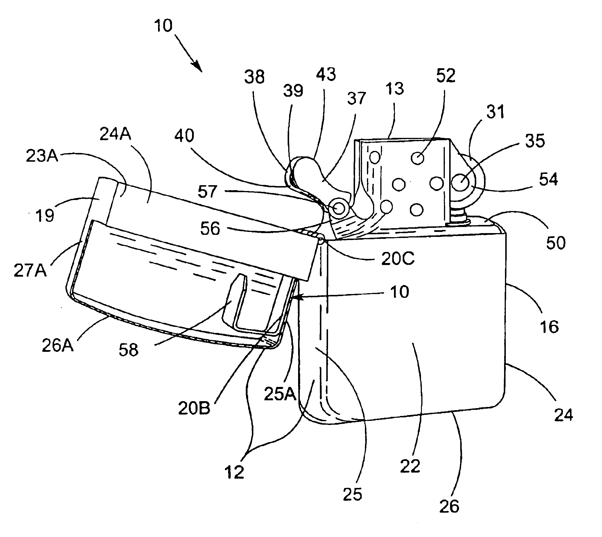
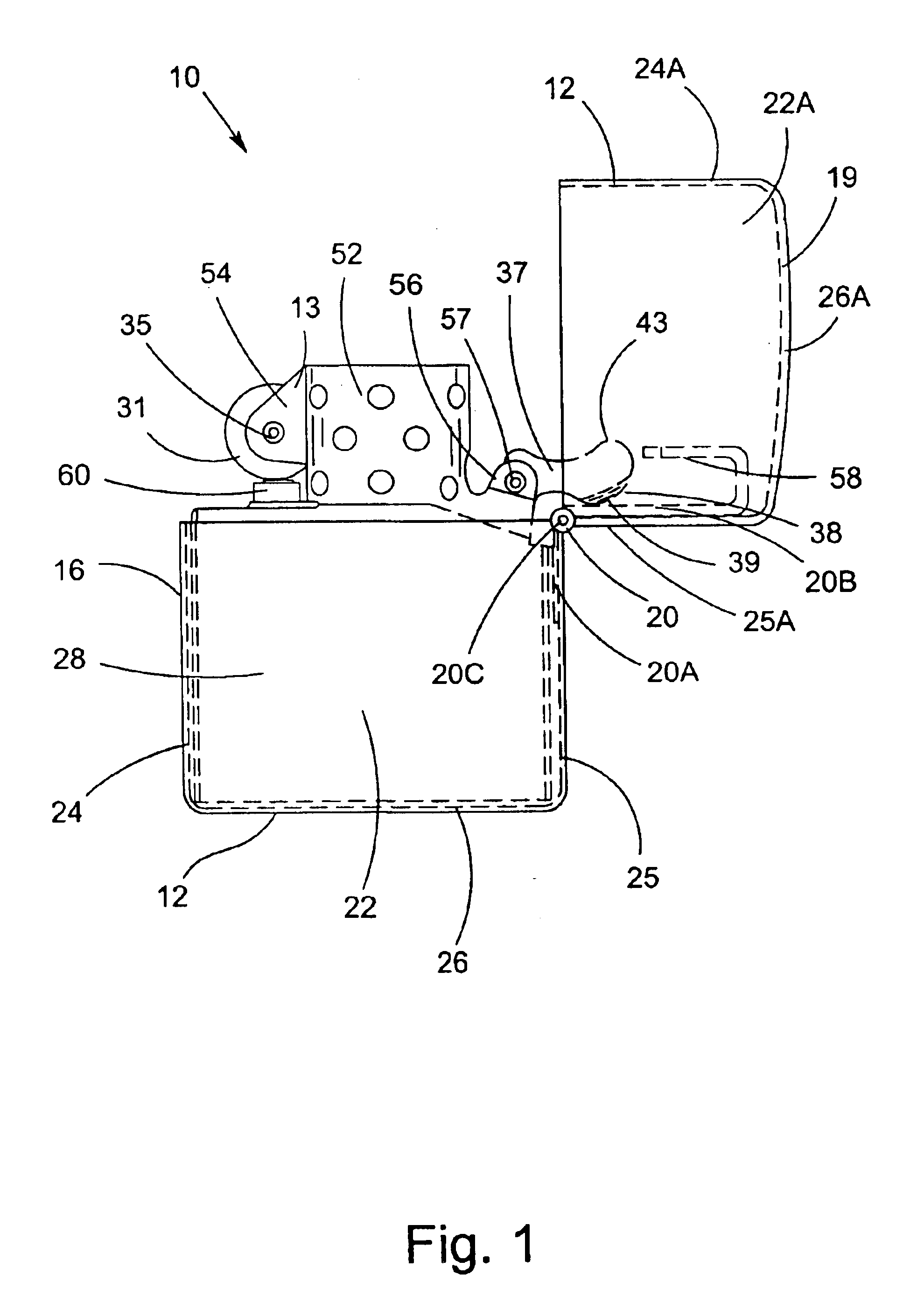
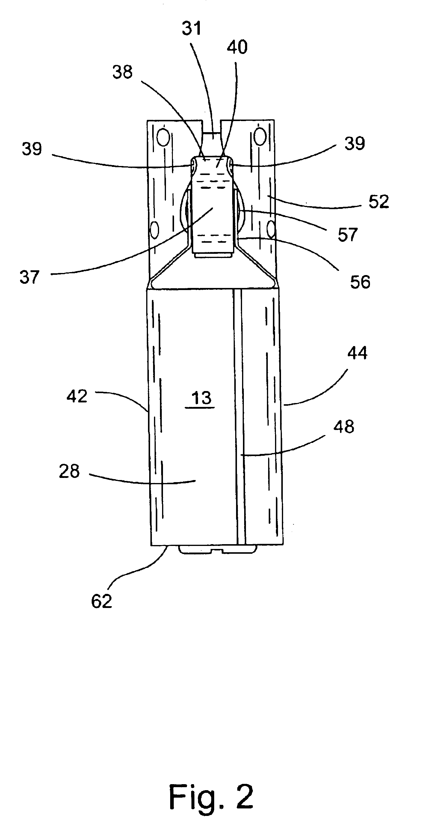
[0030]FIGS. 1-10 show the lighter 10 of the present invention. The invention significantly reduces interference between the cam 37 and curved hinge 20 when the cover or lid 19 of the lighter 10 is opened and closed. This significant reduction in interference is attributed to the curved or rounded portions 39 of the contact surface 38 of the cam 37 that allow for sliding contact between the matching curved surface 21 of the curved hinge 20 and the curved surface of the cam 37, thus reducing interference.

[0031]As shown in FIGS. 1 and 4-8, the lighter 10 comprises a shell 12 having an outer case 16 that is hollow and a cover or lid 19 that is also hollow. A curved hinge 20 is connected to the outer case 16 and lid 19, thus connecting the outer case 16 and lid 19. As shown in FIGS. 1, 4, and 5, 6A, 7, and 8, the outer case 16 has a first side wall 22 disposed in a spaced apart relation to a second side wall 23, a first end wall 24 disposed in a spaced apart relation to a second end wall...


PUM


Abstract

A lighter comprising an outer case having a first sidewall disposed in spaced apart relation to a second sidewall, a first end wall disposed in spaced apart relation to a second end wall, and a base connected to the side walls and end walls. A lid having lid end walls and lid side walls connected to a cover. A curved hinge connecting the outer case and lid. An inside unit is provided and is receivable in the outer case. The inside unit has a plate and front and rear lugs. A cam is mounted to the rear lugs and slides over the curved hinge. The cam has a cam contact surface that has curved portions used for sliding over the curved hinge to thus reduce interference when the lid is opened and closed.

Description

PRIORITY CLAIM[0001]This application claims the benefit of U.S. Provisional Patent Application No. 60 / 450,270, filed on Feb. 27, 2003.FIELD OF THE INVENTION[0002]The present invention relates generally to lighters having curved hinges, and more specifically to a fabricated curved hinged lighter having a cam that provides for decreased interference when the lid of the lighter is opened and closed.BACKGROUND OF THE INVENTION[0003]The design of some reusable lighters incorporates a shell comprising an outer case and a cover or lid. A hinge connects the outer case and lid. Internal to the shell is an inside unit which is the working portion of these lighters. The inside unit can be manually removed from the outer case, loaded with fuel, and then manually reinserted into the outer case.[0004]Such reusable lighters that have a hinge connecting the outer case and lid employ some form of a cam which is integral to the insert. The cam is used to bias against the lid and hold the lid in the c...

Claims


Application Information

Patent Timeline
IPC IPC(8): F23Q2/00F23Q2/40
CPCF23Q2/40
Inventor JOHNSON, MICHAEL WAYNE
Owner ZIPPO MFG
Learn More