

Transmission line used to transmit high-frequency electrical signals
- Summary
- Abstract
- Description
- Claims
- Application Information
AI Technical Summary
Benefits of technology
Problems solved by technology
Method used
Image

Examples
first embodiment
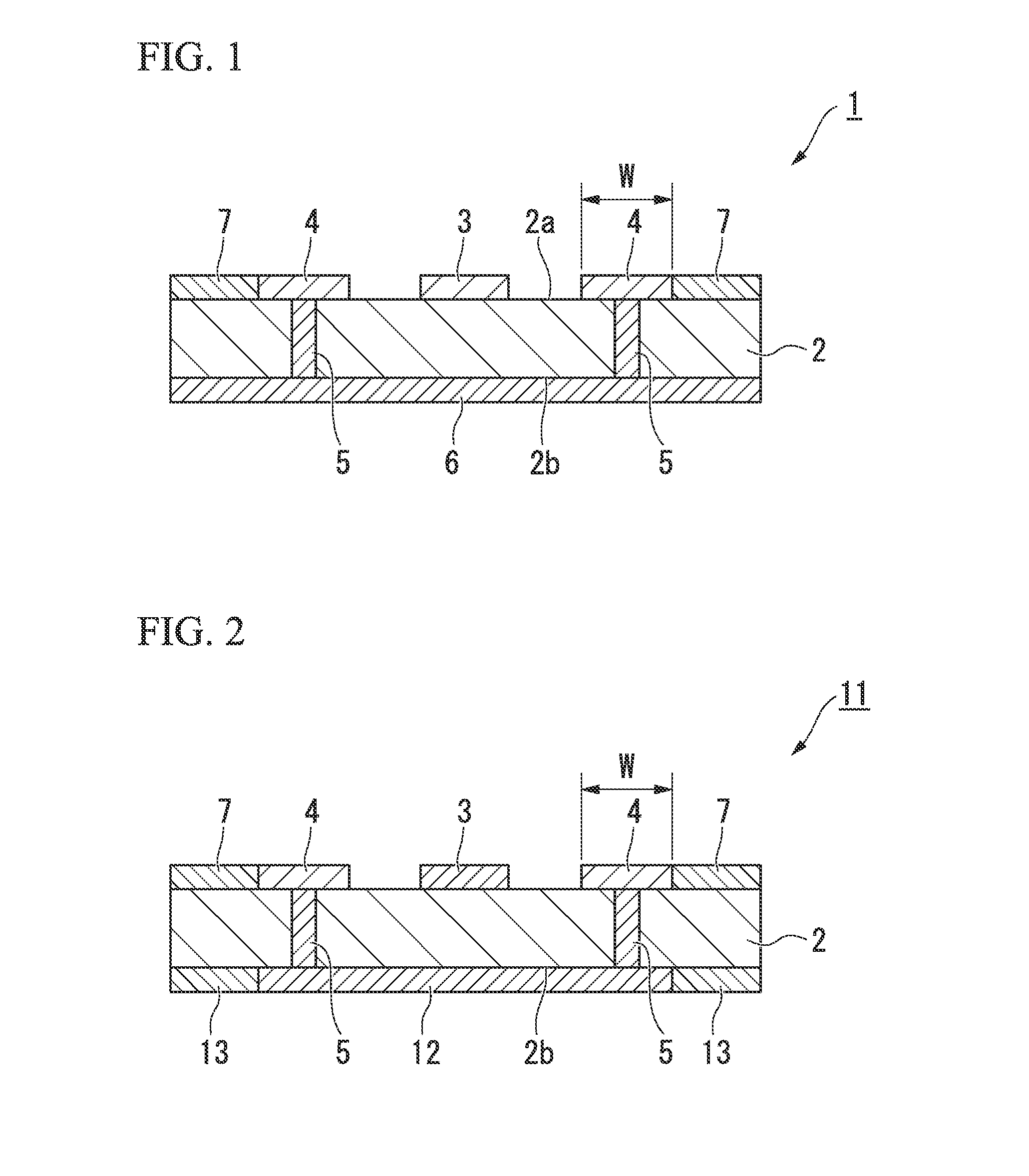
[0042]FIG. 1 is a cross-sectional view of a GCPW-type transmission line used to transmit high-frequency electrical signals according to a first embodiment of the invention, and illustrates a transmission line that can deal with high-frequency electrical signals having frequencies of 20 GHz or higher. In the drawing, reference sign 1 represents a GCP-type transmission line used to transmit high-frequency electrical signals, in which a signal line 3 used to transmit high-frequency electrical signals is formed on a front surface (one principal surface) 2a of a dielectric substrate 2, GND electrodes (first ground electrodes) 4 are formed outside the signal line 3 and in vicinities of end portions of the front surface 2a, and a GND electrode (second ground electrode) 6 that is electrically connected to the GND electrodes 4 through via holes 5 is formed across an entire rear surface (the other principal surface) 2b of the dielectric substrate 2.
[0043]In addition, band-shaped resistors 7 t...
second embodiment
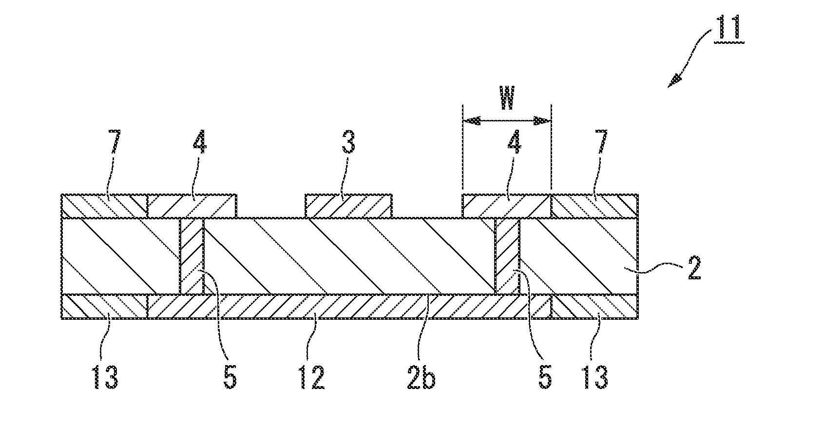
[0058]FIG. 2 is a cross-sectional view of a GCPW-type transmission line used to transmit high-frequency electrical signals according to a second embodiment of the invention, and the differences of the transmission line used to transmit high-frequency electrical signals 11 of the present embodiment from the transmission line used to transmit high-frequency electrical signals 1 of the first embodiment are as follows. While the GND electrode 6 is formed across the entire rear surface 2b of the dielectric substrate 2 in the transmission line used to transmit high-frequency electrical signals 1 of the first embodiment, in the transmission line used to transmit high-frequency electrical signals 11 of the embodiment, a GND electrode (second ground electrode) 12 that has a smaller area than the GND electrode 6 in the first embodiment and is electrically connected to the GND electrodes 4 through the via holes 5 is formed on the rear surface 2b of the dielectric substrate 2, and (second) band...
examples
[0066]Hereinafter, the invention will be specifically described using an example and a conventional example, but the invention is not limited to the examples.
Conventional Example
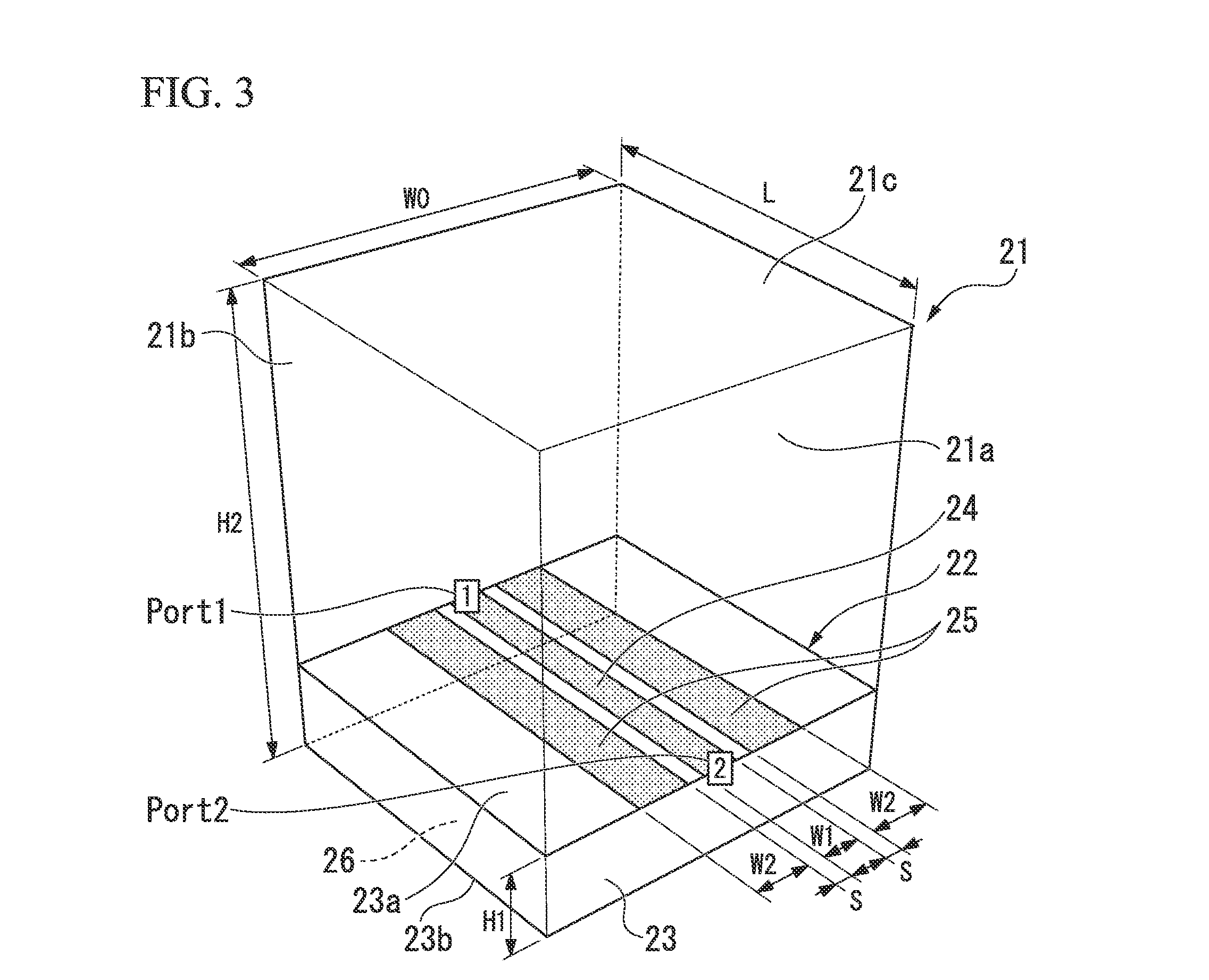
[0067]FIG. 3 is a view illustrating a conventional GCPW-type transmission line used to transmit high-frequency electrical signals (hereinafter, referred to shortly as GCPW-type transmission line) formed in a hexahedral metal box filled with air. In the drawing, reference sign 21 represents the metal box, and has a hexahedral structure formed by assembling metallic walls 21a, 21b, 21c, . . . in a box shape.
[0068]In addition, reference sign 22 represents the GCPW-type transmission line, a signal line 24 used to transmit high-frequency electrical signals is formed on a front surface 23a of a dielectric substrate 23, GND electrodes (first ground electrodes) 25 and 25 are formed outside the signal line 24, and a GND electrode (second ground electrode) 26 that is electrically connected to the GND electrodes 25 and...
PUM
 Abstract
Description
Claims
Application Information