

Invasive sense measurement in prosthesis installation and bone preparation
- Summary
- Abstract
- Description
- Claims
- Application Information
AI Technical Summary
Benefits of technology
Problems solved by technology
Method used
Image

Examples
first embodiment
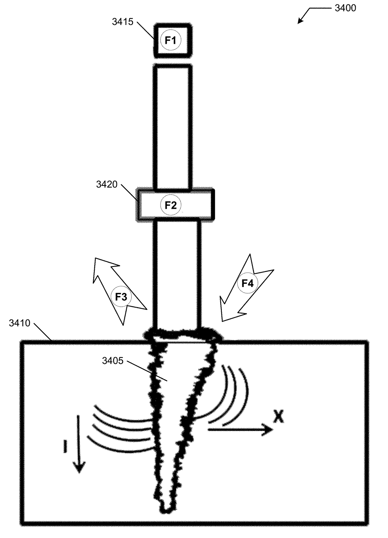
[0272]FIG. 34 illustrates a bone preparation system 3400 applying realtime interface-force evaluation to bone preparation. System 3400 may include a cutting implement 3405 (such as a cutting broach) that is driven into a portion of a bone 3410 to prepare portion of bone 3410, such receipt of a stem of a prosthetic device.
[0273]System 3400 is similar to system 2900 except that system 3400 is a bone preparation tool and in some instances may be used to estimate, during preparation, various forces (e.g., extraction force F4) when an implant is actually installed.
[0274]System 3400 may include a force generator 3415 coupled to a force applicator 3420 that applies operational forces to an implement, such as to cutting broach 3405. Some embodiments described herein may be represented by system 3400. F1 is an applied force from force applicator 3415 and may be measured by system 3400 or provided by a predetermined calibrated force. Force generator 3415 may be integrated with or partially or...
second embodiment
[0282]FIG. 35 illustrates a second embodiment applying realtime interface-force evaluation to bone preparation. Some embodiments may create a better cutting tool, including an addition of ultrasonic energy, to installation and preparation tools as described herein, among other uses create an assisted reaming or broaching or cavity definition of the portion of the bone for obtaining a more precise cut and at a lower tolerance, including addition of the invasive sense measurement concepts disclosed herein. This is believed to be a new and novel idea that can be considered for preparation of the bone for obtaining better tension of the pelvis for application of an acetabular prosthesis and may be used for prediction of F3 / F4 for installed implants or an estimation of a patient-specific modulus of elasticity (K) for bone being prepared which may inform a range of subsequent processing.
[0283]A discussion of a three-dimensional bone sculpting tool, including ultrasonic assist, is further ...
PUM
 Abstract
Description
Claims
Application Information