Force sense measurement in prosthesis installation

Active Publication Date: 2017-07-13
BEHZADI KAMBIZ
View PDF1 Cites 26 Cited by
  • Summary
  • Abstract
  • Description
  • Claims
  • Application Information

AI Technical Summary

Benefits of technology

[0017]Disclosed is a system and method for allowing any surgeon, including those surgeons who perform a fewer number of a replacement procedure as compared to a more experienced surgeon who performs a greater number of procedures, to provide an improved likelihood of a favorable outcome approaching, if not exce

Problems solved by technology

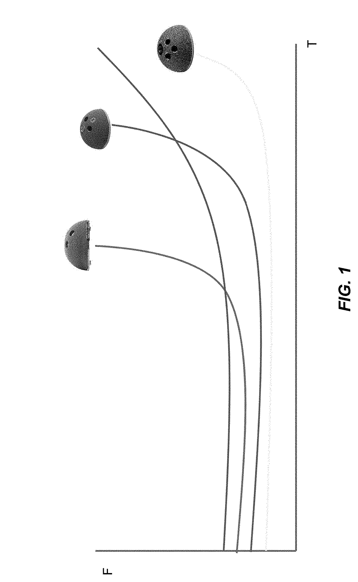
Patients of surgeons who do not perform as many procedures can have increased risks of complications, particularly of complications arising from incorrect placement and positioning of the acetabular component.
The incorrect placement and positioning may arise even when the surgeon understood and intended the acetabular component to be inserted and positioned correctly.
This is true because in some techniques, the tools for actually installing the acetabular component are crude and provide an imprecise, unpredictable coarse positioning outcome.
However the resulting location and orientation of the acetabular component after the adjustment may not be, in fact, the desired location and/or orientation.
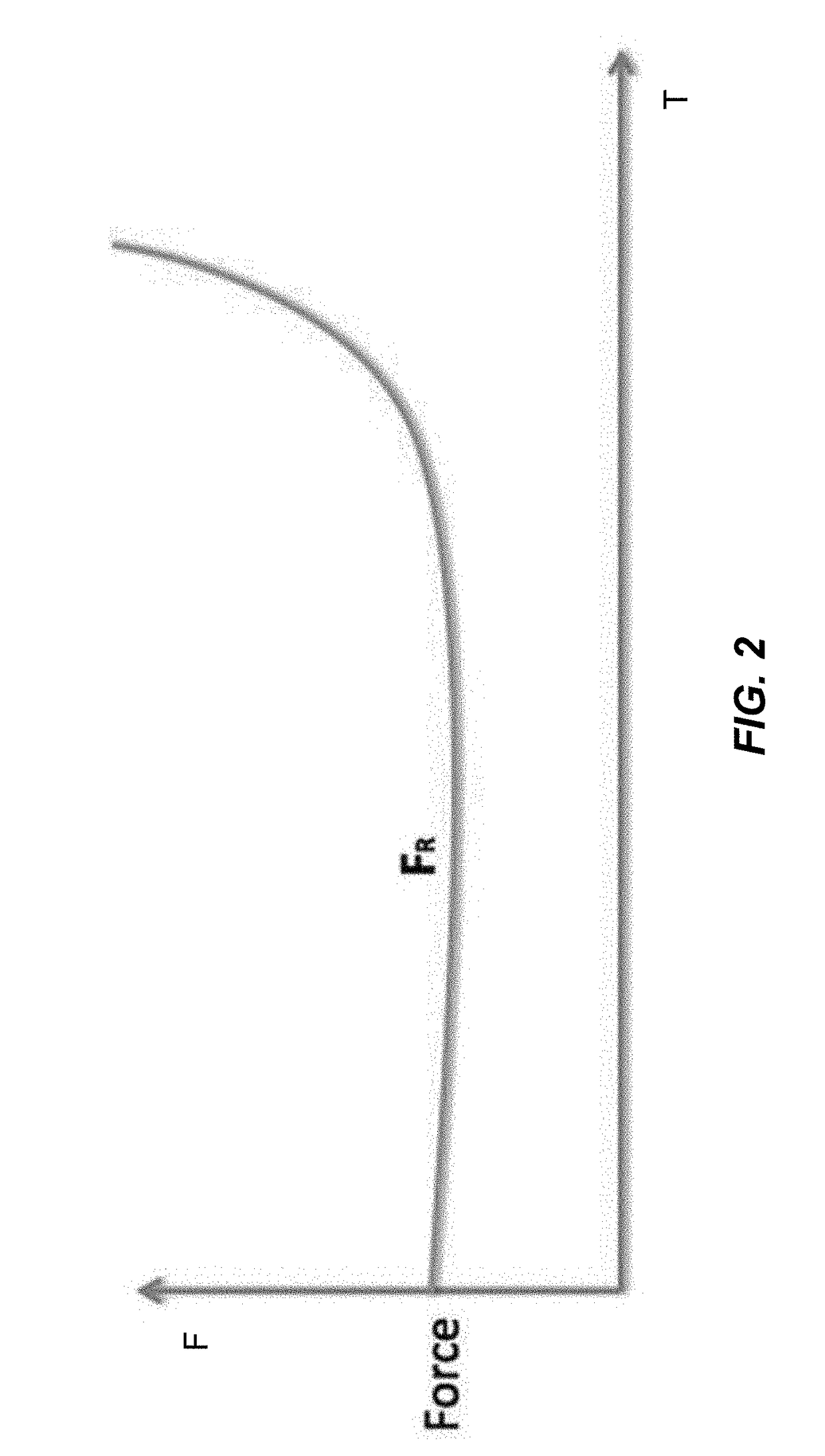
In some circumstances, quite large impacting forces are applied to the prosthesis by the mallet striking the rod; these forces make fine tuning difficult at best and there is risk of fracturing and/or shattering the acetabulum during these impacting steps.
Even though hip replacement surgery has been one of the most successful operations, it continues to be plagued with a problem of inconsistent acetabular cup placement.
Cup mal-positioning is the single greatest cause of hip instability, a major factor in polyethylene wear, osteolysis, impingement, component loosening and the need for hip revision surgery.
These incorporated patents explain that the process of cup implantation with a mallet is highly unreliabl

Method used


Image

  • Force sense measurement in prosthesis installation
  • Force sense measurement in prosthesis installation
  • Force sense measurement in prosthesis installation

Examples


Example

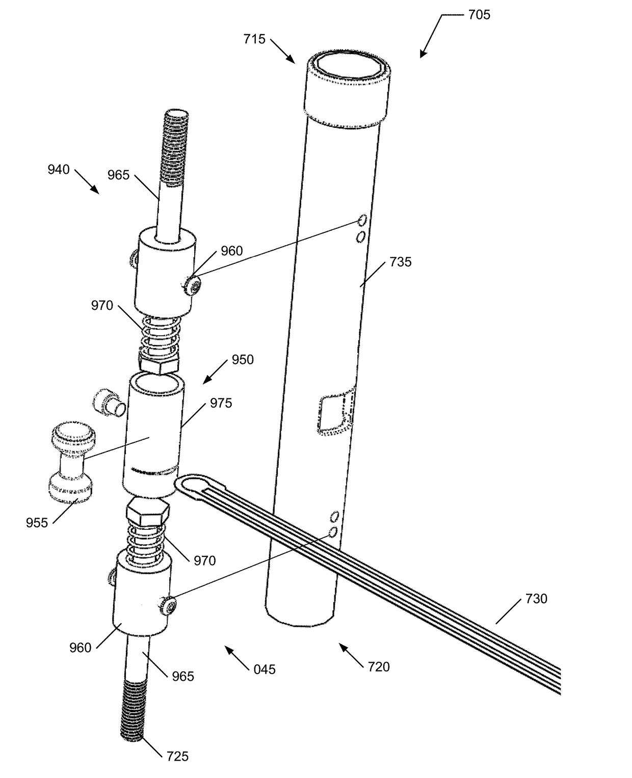
[0070]Embodiments of the present invention provide a system and method for allowing any surgeon, including those surgeons who perform a fewer number of a replacement procedure as compared to a more experienced surgeon who performs a greater number of procedures, to provide an improved likelihood of a favorable outcome approaching, if not exceeding, a likelihood of a favorable outcome as performed by a very experienced surgeon with the replacement procedure, such as by understanding the prosthesis installation environment (e.g., cup / cavity interface) and to provide intelligent and interactive tools and methods to standardize the installation process. The following description is presented to enable one of ordinary skill in the art to make and use the invention and is provided in the context of a patent application and its requirements.

[0071]Various modifications to the preferred embodiment and the generic principles and features described herein will be readily apparent to those skil...


PUM


Abstract

A system and method for allowing any surgeon, including those surgeons who perform a fewer number of a replacement procedure as compared to a more experienced surgeon who performs a greater number of procedures, to provide an improved likelihood of a favorable outcome approaching, if not exceeding, a likelihood of a favorable outcome as performed by a very experienced surgeon with the replacement procedure. Force sensing is included to aid in quantifying installation of an implant, particularly a cup into a pelvic bone.

Description

CROSS REFERENCE TO RELATED APPLICATIONS[0001]This application is a continuation-in-part of U.S. patent application Ser. No. 15 / 202,434 and claims benefit of two US Provisional Applications including U.S. Patent Application No. 62 / 353,024 and U.S. Patent Application No. 62 / 355,657 and is related to the following: a) U.S. Patent Application No. 61 / 921,528, b) U.S. Patent Application No. 61 / 980,188, c) U.S. patent application Ser. No. 14 / 584,656, d) U.S. patent application Ser. No. 14 / 585,056, and U.S. Patent Application No. 62 / 277,294, the contents of each of these applications in their entireties are hereby expressly incorporated by reference thereto for all purposes.FIELD OF THE INVENTION[0002]The present invention relates generally to orthopedic surgical systems and procedures employing a prosthetic implant for, and more specifically, but not exclusively, to joint replacement therapies such as total hip replacement including controlled installation and positioning of the prosthesis...

Claims


Application Information

Patent Timeline
IPC IPC(8): A61F2/46A61F2/34
CPCA61F2/4609A61F2/34A61F2/4657A61F2002/4632A61F2002/4681A61F2002/4688A61F2002/4666A61B17/1666A61B17/142A61F2002/30565A61F2002/469A61F2002/4694A61B34/20A61F2/3609A61F2/4637A61F2002/30525A61F2002/30617A61F2002/30718A61F2002/3627A61F2002/365A61F2002/4627A61F2002/4629A61F2002/4671A61F2250/006A61F2/4607A61F2/3662A61F2002/30604A61F2002/3611A61F2002/3625A61F2002/4687A61F2/4603
Inventor BEHZADI, KAMBIZLEITE, ALEXANDRE CARVALHORUSK, JESSE
Owner BEHZADI KAMBIZ
Why Eureka
Try Eureka