Input device and method for controlling input device

a technology of input device and input device, which is applied in the direction of mechanical control device, controlling member, instrument, etc., can solve the problems of increasing the size of the input device and generating contact sound

Active Publication Date: 2018-03-29
KURIMOTO LTD
View PDF30 Cites 5 Cited by
  • Summary
  • Abstract
  • Description
  • Claims
  • Application Information

AI Technical Summary

Problems solved by technology

However, using a motor as in Japanese Laid-Open Patent Publication No. 2003-050639 has a disadvantage that the size of the input device increases.
Also, using a frictional force as in Japanese Laid-Open Patent Publication No. 2015-008593 has a disadvantage that a contact sound is generated when the solids in a noncontact state are brought into contact with each other.

Method used


Image

  • Input device and method for controlling input device
  • Input device and method for controlling input device
  • Input device and method for controlling input device

Examples


first embodiment

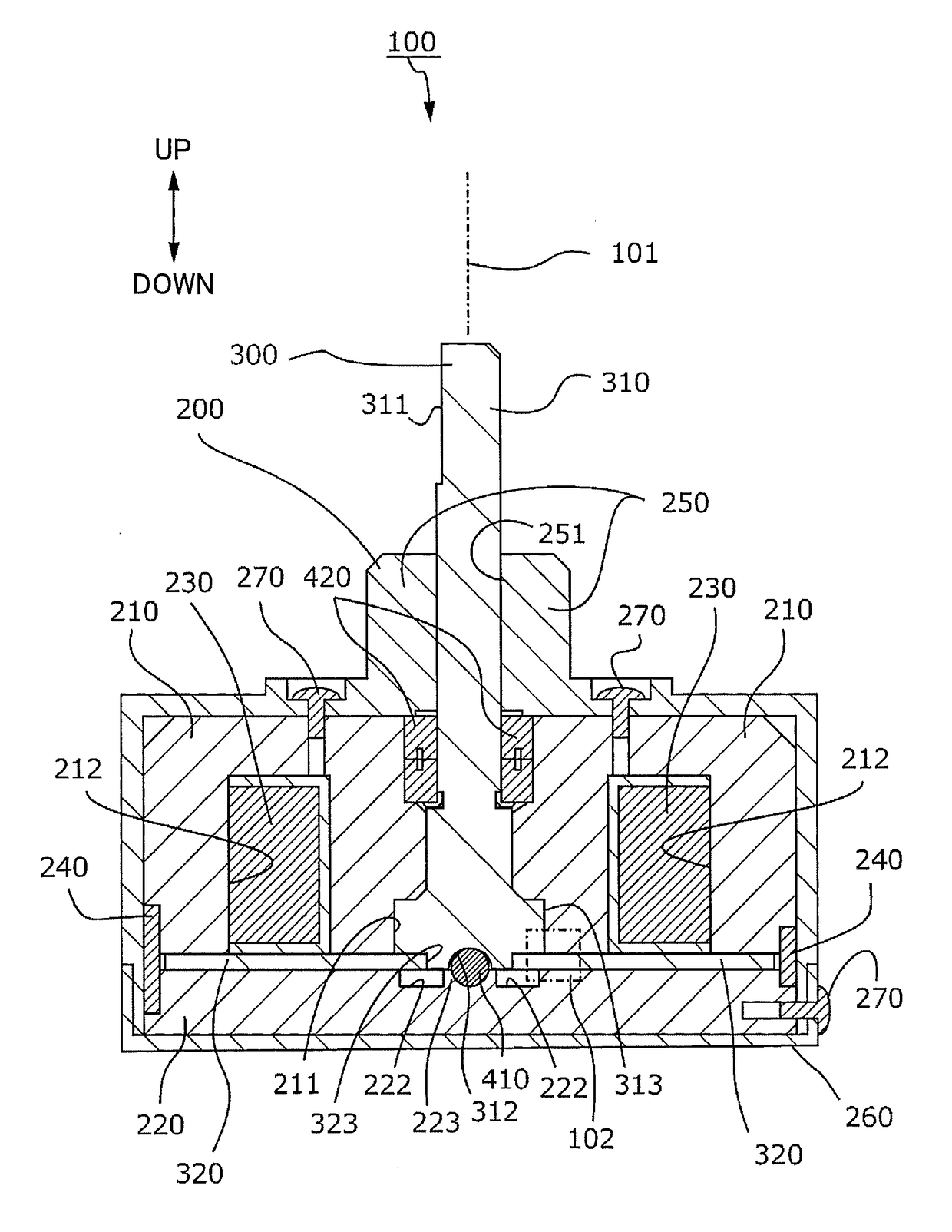
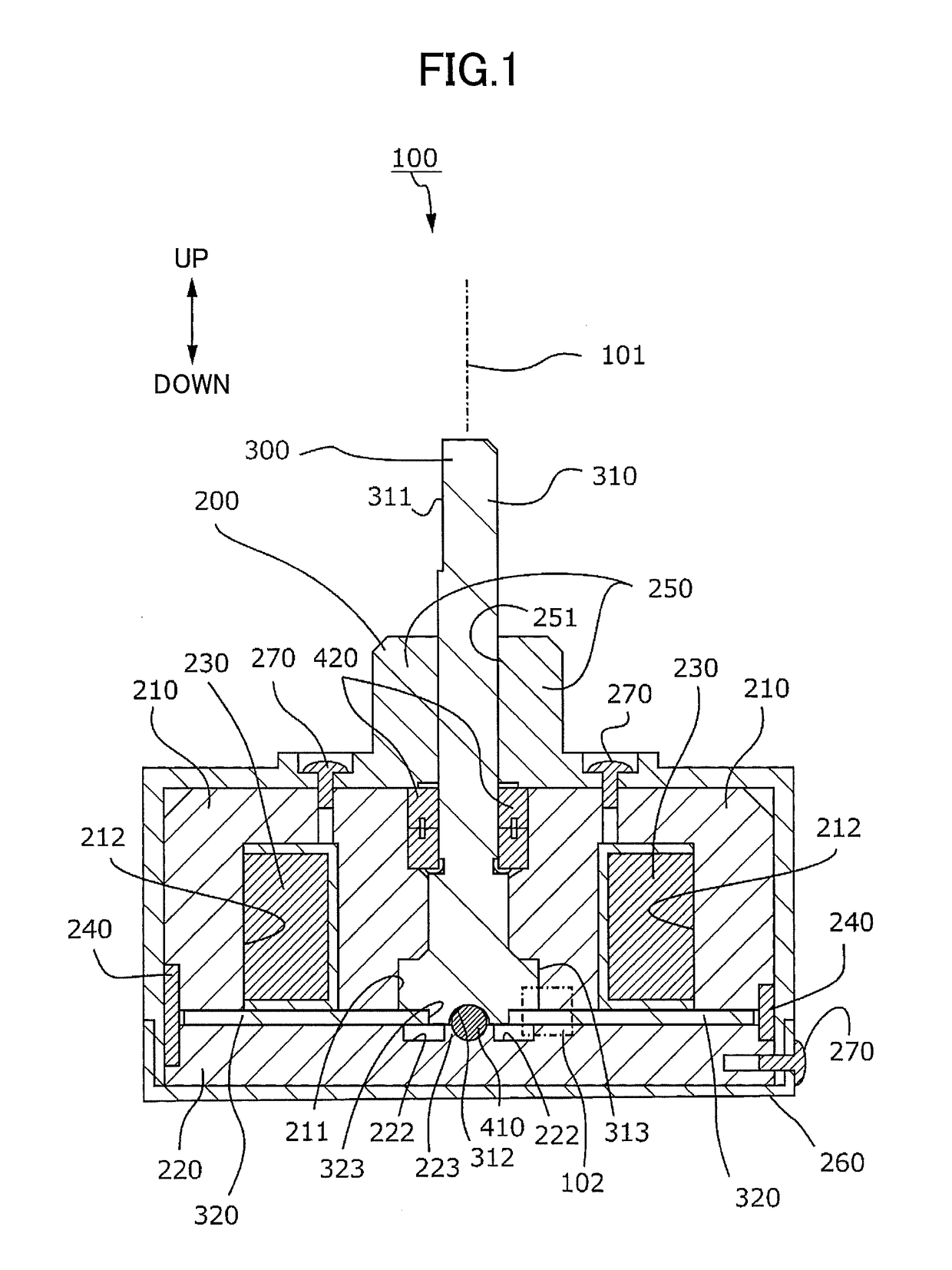
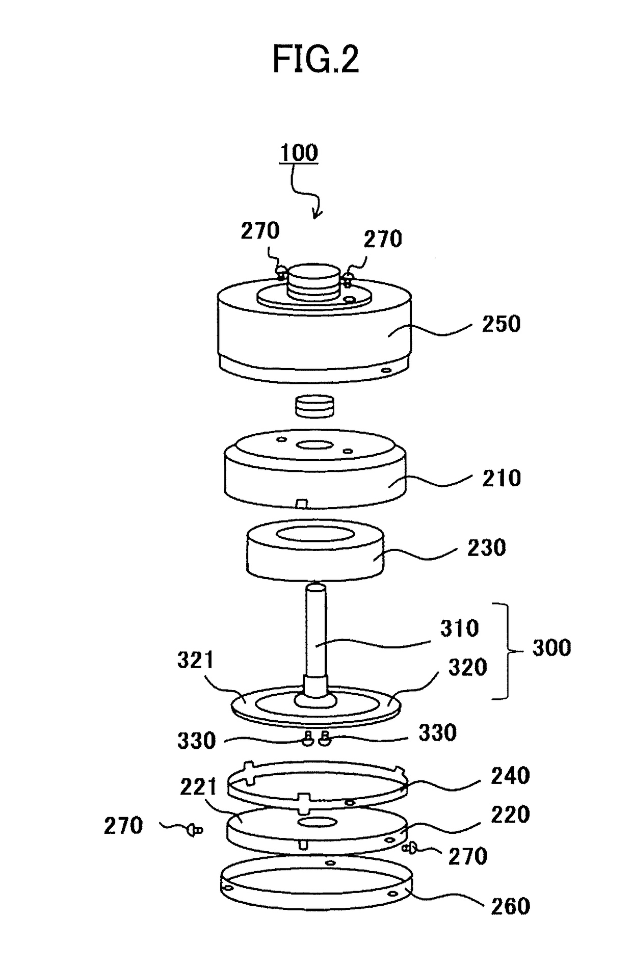
[0017]An input device 100 according to the present invention is described below. FIG. 1 is a cross-sectional view of the input device 100 taken along a plane including a central axis 101 of rotation and seen in a direction that is orthogonal to the central axis 101. FIG. 2 is an exploded perspective view of the input device 100. FIG. 3 is a partial enlarged view of an area 102 of the input device 100 in FIG. 1.

[0018]In FIGS. 1 through 3, for descriptive purposes, a direction along the central axis 101 is defined as the vertical direction. However, this does not limit the direction of the input device 100 when the input device 100 is actually used. A radial direction indicates a direction that is orthogonal to and extending away from the central axis 101.

[0019]As illustrated in FIG. 1, the input device 100 includes a first part 200 and a second part 300 that rotate relative to each other in both directions around the central axis 101, a spherical part 410, and an annular bearing 420....

second embodiment

[0068]FIG. 8 illustrates an input device 800 according to a FIG. 8 is a cross-sectional view of the input device 800 taken along a plane including a central axis 801. For descriptive purposes, a direction along the central axis 801 is defined as the vertical direction. However, this does not limit the direction of the input device 800 when the input device 800 is actually used.

[0069]A radial direction indicates a direction that is orthogonal to and extending away from the central axis 801. The input device 800 includes a first part 810 and a second part 820 that rotate relative to each other in both directions around the central axis 801, an annular bearing 830, and a magnetic viscous fluid 860.

[0070]The first part 810 includes a first fixed yoke 811, a second fixed yoke 812, a third fixed yoke 813, a magnetic-field generator 814, an annular part 815, a lid 816, and an end bearing 817.

[0071]A recess 840 is formed in a lower-outer side of the first fixed yoke 811. The recess 840 has...


PUM


Abstract

An input device includes a first part and a second part configured to move relative to each other according to an input operation, a magnetic viscous fluid whose viscosity changes according to a magnetic field, and a magnetic-field generator that generates the magnetic field applied to the magnetic viscous fluid. The second part includes a first surface and a second surface that are arranged in a direction orthogonal to a direction of relative movement between the first part and the second part. Gaps are formed between the first surface and the first part and between the second surface and the first part, and the magnetic viscous fluid is present in at least a part of the gaps.

Description

CROSS-REFERENCE TO RELATED APPLICATIONS[0001]The present application is a continuation application filed under 35 U.S.C. 111(a) claiming benefit under 35 U.S.C. 120 and 365(c) of PCT International Application No. PCT / JP2016 / 067656, filed on Jun. 14, 2016, which is based on and claims the benefit of priority of Japanese Patent Application No. 2015-124661 filed on Jun. 22, 2015, the entire contents of which are incorporated herein by reference.BACKGROUND OF THE INVENTION1. Field of the Invention[0002]An aspect of this disclosure relates to an input device and a method for controlling the input device.2. Description of the Related Art[0003]There are known input devices that provide a dynamic operational sensation (or operation feeling) to an operator when the operator operates one of two components that rotate relative to each other. Japanese Laid-Open Patent Publication No. 2003-050639 discloses an input device that generates an operation feeling by generating torque with a motor in a...

Claims


Application Information

Patent Timeline
Patent Type & Authority Applications(United States)
IPC IPC(8): H01H36/00G05G1/10G05G5/03
CPCH01H36/008G05G1/10G05G5/03
Inventor WAKUDA, HIROSHITAKAHASHI, KAZUNARIGOTO, ATSUSHIYASUHARA, RYUICHIRO
Owner KURIMOTO LTD
Why Eureka
Try Eureka