Sharpener

a pencil and sharpening technology, applied in the field of pencils, can solve the problems of inability to easily produce pencils b>100/b>, and possible breakage of pencils b>102/b>, and achieve the effect of smooth sharpening, easy reaching of pencils, and smooth sharpening

Active Publication Date: 2018-05-03
TOKIWA CORP
View PDF10 Cites 0 Cited by
  • Summary
  • Abstract
  • Description
  • Claims
  • Application Information

AI Technical Summary

Benefits of technology

[0013]The main body may include a fixing member to which the blade portion is fixed, and a cover which accommodates the fixing member and has the guide hole formed therein. In this case, the guide hole guides the tip portion of the pencil to the blade portion, and brings the tip portion of the pencil into contact with the fixed blade portion. The blade portion is fixed to the fixing member. Thus, the tip portion can be more reliably brought into contact with the blade portion. That is, a position of the blade portion can be stabilized, and the tip portion of the pencil can be more reliably brought into contact with the blade portion. Therefore, the tip portion of the pencil can be more smoothly sharpened.
[0014]The blade portion may have a first surface extending from a blade edge, and a second surface forming an acute angle with the first surface and having an area smaller than an area of the first surface. The blade portion may be installed so that the second surface faces away from the pencil. In this case, an acute angle portion of the blade edge faces the pencil, thereby enabling the blade edge to easily reach the pencil. Therefore, compared to a case where the acute angle portion of the blade edge faces away from the pencil, the tip portion of the pencil can be more smoothly sharpened.
[0015]The pencil may have a lead and a covering portion for covering the lead. The blade portion may sharpen both the lead and the covering portion of the inserted pencil. In this case, the tip portion of the pencil is brought into contact with the blade portion, thereby enabling the blade portion to sharpen both the lead and the covering portion. Therefore, the tip portion of the pencil can be efficiently sharpened.
[0016]The guide hole may have a first inner peripheral portion shaped to correspond with an outer periphery of the pencil, and a second inner peripheral portion located on the blade portion side of the guide hole. The second inner peripheral portion forms a shape spreading outward from the first inner peripheral portion. In this case, the guide hole includes the first inner peripheral portion shaped along the outer periphery of the pencil opposite to the blade portion. In this manner, movement of the pencil that is inserted into the guide hole can be regulated or limited in the radial direction. Accordingly, in a stable state, the pencil can be inserted into the guide hole. Therefore, the tip portion of the pencil can be smoothly sharpened. The guide hole includes the second inner peripheral portion located on the blade portion side and forming the shape spreading from the first inner peripheral portion. In this manner, even if the position of the pencil inserted into the guide hole is inclined in the axial direction, contact between the pencil and a wall surface of the guide hole may be minimized. That is, in a case where an inner periphery of the guide hole is shaped along the outer periphery of the pencil, the pencil comes into contact with the wall surface of the guide hole when the pencil is inserted into the guide hole. Thus, the pencil may not be efficiently sharpened in some cases. In contrast, as described above, in a case where the guide hole includes the spread second inner peripheral portion, a configuration can be adopted in which the pencil is less likely to come into contact with the wall surface of the guide hole even if the pencil is inclined. Accordingly, the pencil can be more smoothly inserted into the guide hole. Therefore, the pencil can be more efficiently sharpened.
[0017]According to the present invention, it is possible to easily produce a pencil having a planar portion formed at a tip portion, and it is possible to suppress uneven quality of the pencil.

Problems solved by technology

Consequently, it takes time to produce the pencil 100, and actually, the pencil 100 cannot be easily produced.
For example, in a case where an unskilled producer produces the pencil 100, a problem arises in that the lead 102 may be broken while being sharpened or the pencil 100 may not be satisfactorily sharpened.
Thus, the pencil may not be efficiently sharpened in some cases.

Method used


Image

  • Sharpener
  • Sharpener
  • Sharpener

Examples


Embodiment Construction

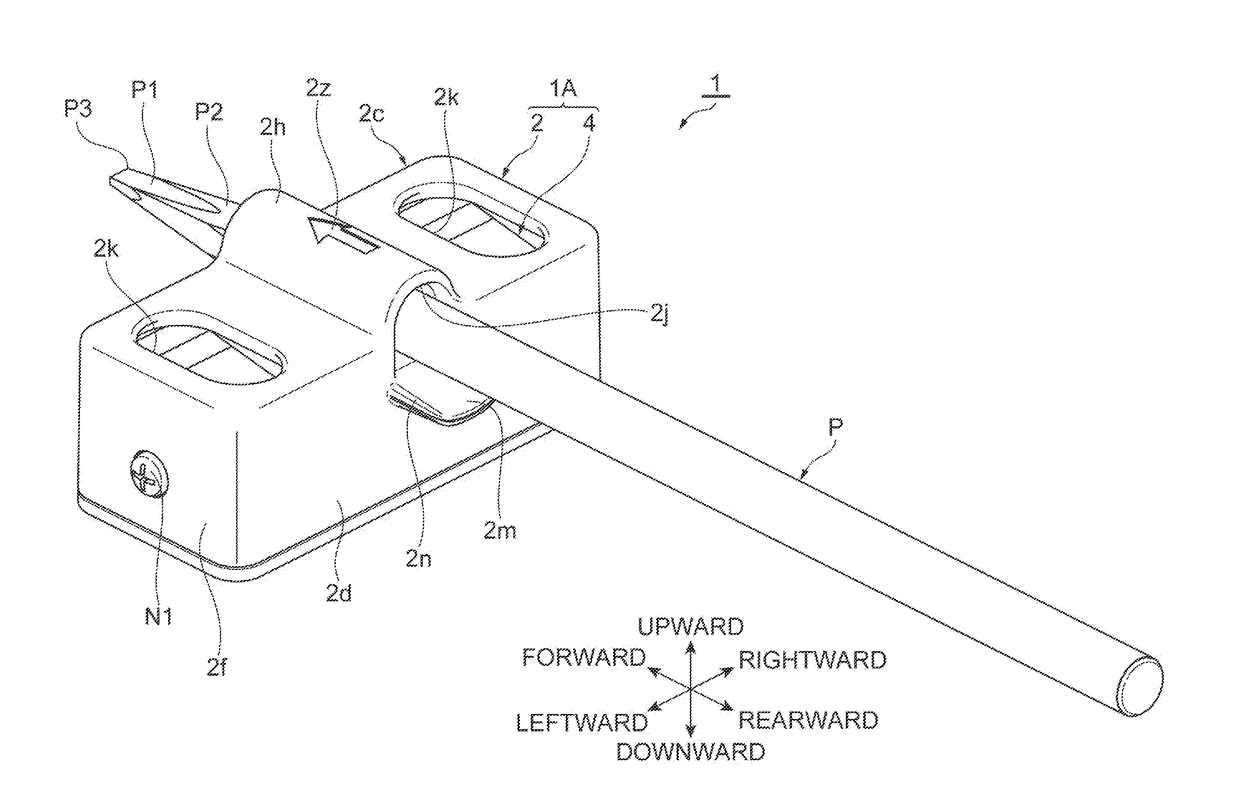
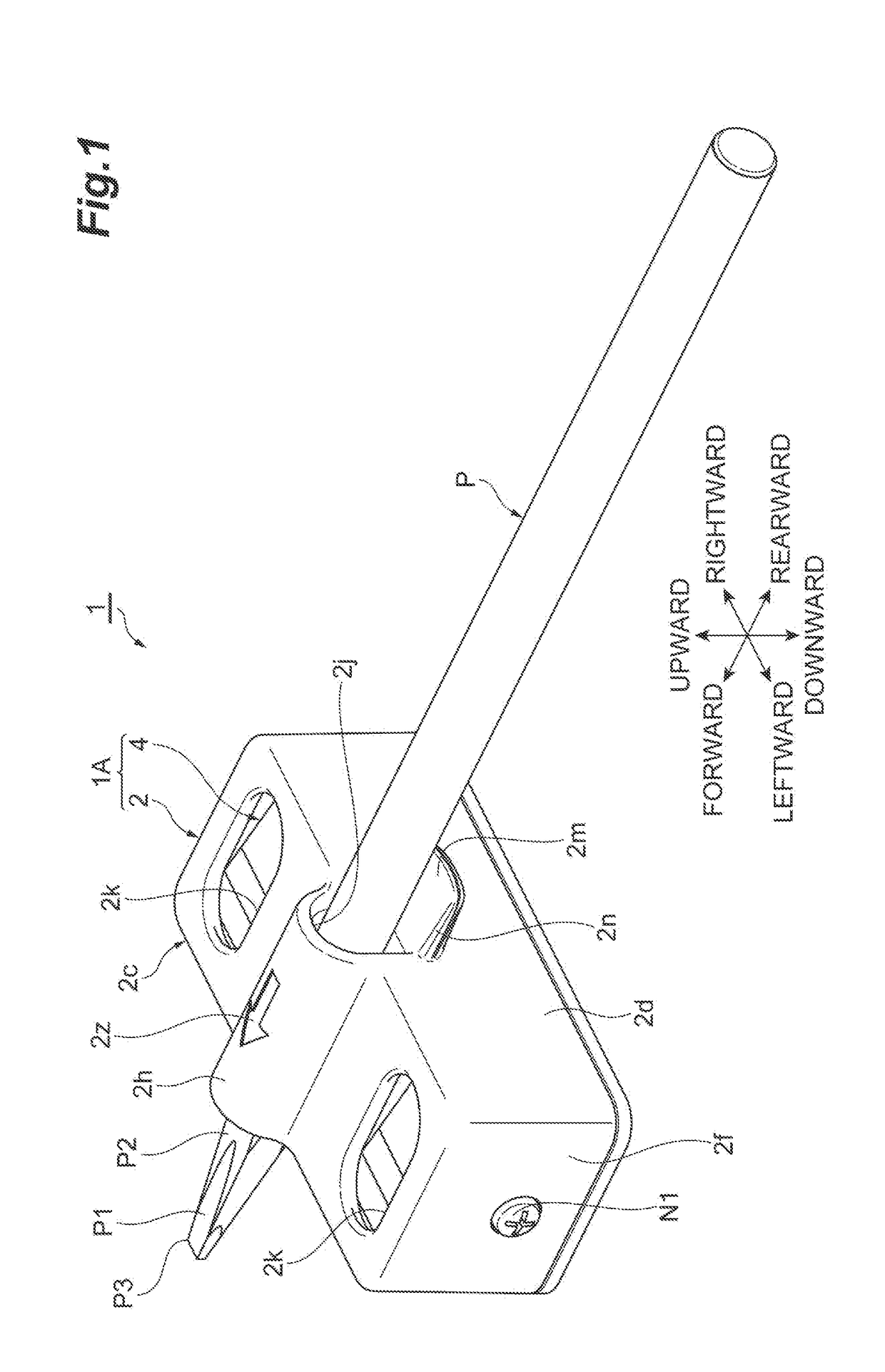
[0040]Hereinafter, embodiments of a sharpener according to the present invention will be described with reference to the drawings. In the following description, the same reference numerals will be given to the same or corresponding elements, and repeated description will be omitted.

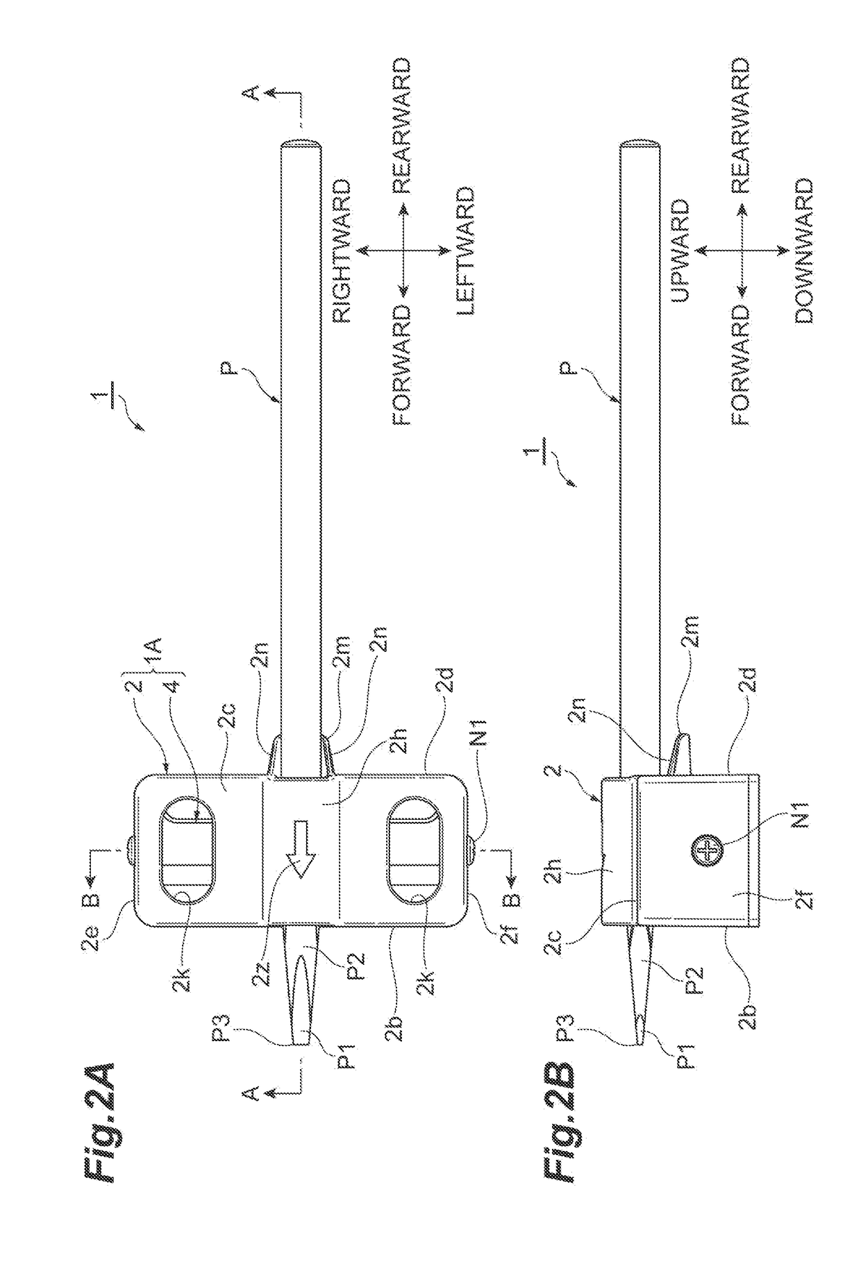
[0041]FIG. 1 is a perspective view illustrating a sharpener and a pencil according to one or more embodiments. FIG. 2A is a plan view illustrating the sharpener and the pencil in FIG. 1. FIG. 2B is a side view illustrating the sharpener and the pencil in FIG. 1. FIG. 3 is a sectional view taken along line A-A in FIG. 2A. As illustrated in FIGS. 1 to 3, a sharpener 1 according to one or more embodiments is used when a pencil P is sharpened.

[0042]The pencil P forms a bar shape whose entire shape is elongated, and has a round bar shape. In one or more embodiments, the pencil P is sharpened into a long sword shape by the sharpener 1. Here, the long sword shape shows a shape of the pencil P sharpened along a p...


PUM


Abstract

The sharpener includes a main body into which the tip portion of the pencil is inserted, and a blade portion installed inside the main body. The tip portion of the pencil is inserted into the main body, and a guide hole for guiding the tip portion of the inserted pencil to the blade portion is formed in the main body. The pencil slides in the guide hole in an axial direction, and the blade portion sharpens the tip portion of the pencil along a plane inclined with respect to the axial direction.

Description

CROSS-REFERENCE TO RELATED APPLICATIONS[0001]This application claims the benefit of priority from Japanese Patent Application No. 2016-215499, filed Nov. 2, 2016, the entire contents of which are incorporated herein by reference.BACKGROUND OF THE INVENTIONField of the Invention[0002]The present invention relates to a sharpener for sharpening a tip portion of a pencil.Related Background Art[0003]In the related art, various sharpeners are known as a sharpener for sharpening a tip portion of a conventional pencil. For example, Japanese Unexamined Utility Model Publication No. 1-158196 discloses a polisher for polishing a drawing pencil. This polisher includes an outer housing, an inner housing movable with respect to the outer housing, a pencil insertion hole formed so as to penetrate the outer housing, and a cutter located at a position facing the pencil insertion hole of the inner housing.[0004]In this polisher, the tip portion of a pencil is inserted into the pencil insertion hole, ...

Claims


Application Information

Patent Timeline
Patent Type & Authority Applications(United States)
IPC IPC(8): B43L23/08
CPCB43L23/085B43L23/06
Inventor TANI, YOSHIKAZU
Owner TOKIWA CORP
Why Eureka
Try Eureka