Autostereoscopic 3-dimensional display

a three-dimensional display and display technology, applied in the field of autostereoscopic three-dimensional display, can solve problems such as uneven luminance, and achieve the effect of remarkable variations in luminance and no luminance variation

Active Publication Date: 2018-05-31
LG DISPLAY CO LTD
View PDF6 Cites 0 Cited by
  • Summary
  • Abstract
  • Description
  • Claims
  • Application Information

AI Technical Summary

Benefits of technology

[0028]The present disclosure also provides a lenticular lens type autostereoscopic 3D display that provides the 3D images by separating multi views generated by the pixel area on the display panel using a lens film in which a plurality of lenticular lenses having a plurality of the view areas is arrayed in series. Particularly, when each of the apertures allocated at each of the pixels is disposed as corresponding to each of the view areas of the lenticular lens, the slanted axis of the lenticular lens is parallel to the diagonal axis of the aperture area. As a result, when observing the stereoscopic image with moving over the whole display area, there is no luminance variation. The lenticular lens type autostereoscopic 3D display according to the present disclosure provides a natural and / or smooth stereoscopic image without remarkable variations on the luminance as the observer moves across the display area.

Problems solved by technology

In the process of manufacturing the display panel having this structure, the luminance unevenness may occur due to the manufacturing process tolerance.

Method used


Image

  • Autostereoscopic 3-dimensional display
  • Autostereoscopic 3-dimensional display
  • Autostereoscopic 3-dimensional display

Examples


first embodiment

[0040]Hereinafter, referring to FIG. 3, the first embodiment of the present disclosure will be explained. FIG. 3 is a plane view illustrating a lenticular lens type autostereoscopic 3D display according to the first embodiment of the present disclosure. All the components of the lenticular lens type autostereoscopic 3D display according to all embodiments of the present disclosure are operatively coupled and configured.

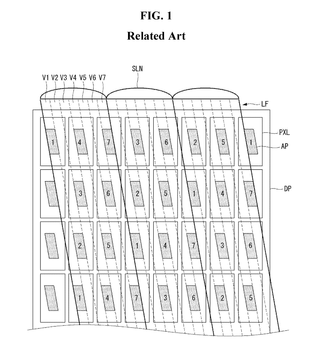
[0041]Referring to FIG. 3, the lenticular lens type autostereoscopic 3D display according to the first embodiment of the present disclosure comprises a display panel DP and a lens film LF disposed on the upper surface of the display panel DP. The display panel DP includes a plurality of the pixels P×L arrayed in a matrix manner. Further, the display panel DP includes various elements for driving the pixels PXL. Each pixel PXL includes one aperture area AP.

[0042]The lens film LF includes a plurality of lenticular lenses SLN having a semi-cylindrical shape and disposed ...

second embodiment

[0051]Hereinafter, referring to FIG. 5, the second embodiment of the present disclosure will be explained. FIG. 5 is an enlarged plane view illustrating a relationship between the structure of an aperture and the structure of the lenticular lens, according to the second embodiment of the present disclosure.

[0052]Referring to FIG. 5, an aperture area AP is defined or allocated in one pixel PXL. The aperture area AP has the parallelogram shape. It is preferable that the lateral width of the aperture area AP is same with the lateral width of one view area defined in the lenticular lens SLN.

[0053]It is preferable that the slanted axis LAX of the lenticular lens SLN is parallel to or corresponding to any one diagonal axis of the aperture area AP. In FIG. 5, the dotted lines inside of the lenticular lens SLN are the imaginary lines for dividing the view areas. These dotted lines are parallel to the slanted axis LAX of the lenticular lens SLN. It is preferable that the slanted line LAX is ...

third embodiment

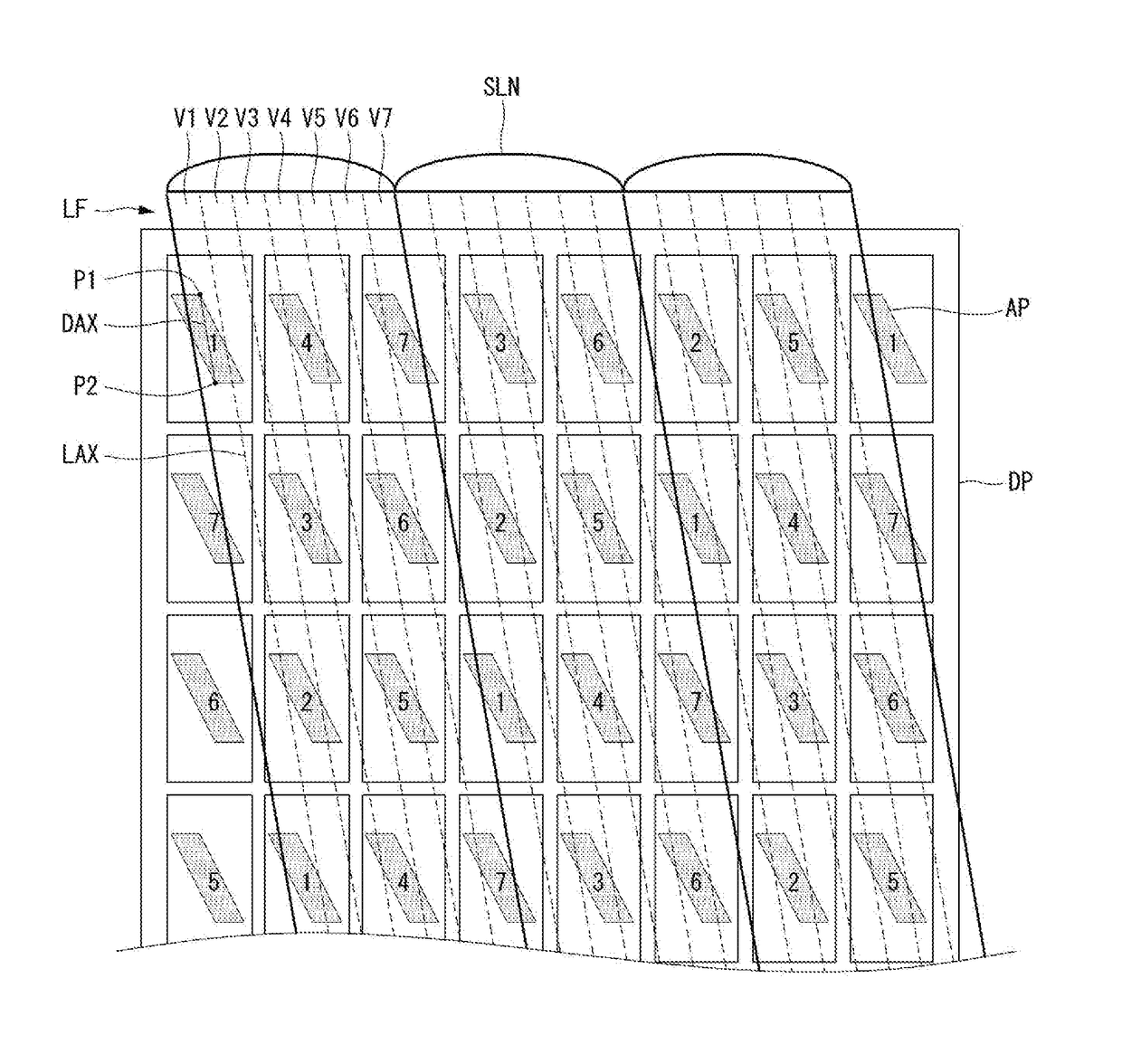
[0063]Hereinafter, referring to FIG. 7, the third embodiment of the present disclosure will be explained. In the third embodiment, a lenticular lens type autostereoscopic 3D display in which the cross-talk area would be much more reduced will be discussed. FIG. 7 is a plane view illustrating a lenticular lens type autostereoscopic 3D display according to the third embodiment of the present disclosure.

[0064]Referring to FIG. 7, the lenticular lens type autostereoscopic 3D display according to the third embodiment of the present disclosure comprises a display panel DP and a lens film LF disposed on the upper surface of the display panel DP. The display panel DP includes a plurality of the pixels P×L arrayed in a matrix manner. Further, the display panel DP includes various elements for driving the pixels PXL. Each pixel PXL includes one aperture area AP.

[0065]The lens film LF includes a plurality of lenticular lenses SLN having a semi-cylindrical shape and disposed continuously in lat...


PUM


Abstract

The present disclosure relates to an autostereoscopic three-dimensional (3D) display in which the multi view structure is configured by using a lenticular lens. The autostereoscopic 3D display includes a display panel including a plurality of pixels, and an aperture area disposed at each pixel; and a lens film disposed on a front surface of the display panel and including a plurality of lenticular lenses, the lenticular lenses having a slanted axis and continuously arrayed along to a lateral direction, wherein the aperture area includes a parallelogram shape, and wherein the slanted axis is parallel with any one diagonal axis of the aperture area.

Description

CROSS-REFERENCE TO RELATED APPLICATIONS[0001]This application claims the priority benefit of Korea Patent Application No. 10-2016-0162358 filed on Nov. 30, 2016 in the Republic of Korea, which is incorporated herein by reference for all purposes as if fully set forth herein.BACKGROUNDTechnical Field[0002]The present disclosure relates to an autostereoscopic three-dimensional (3D) display in which the multi view structure is configured by using a lenticular lens (also referred to hereinafter as a ‘lenticular lens type’). In particular, the present disclosure relates to a lenticular lens type autostereoscopic 3D display representing high quality 3D images in which the brightness differences between the view areas are uniformed regardless of the tolerances of the manufacturing process.Description of the Related Art[0003]Due to the development of the stereoscopic image display technologies, a stereoscopic image reproducing technique is applied to a display device such as a television or...

Claims


Application Information

Patent Timeline
Patent Type & Authority Applications(United States)
IPC IPC(8): H04N13/04
CPCH04N13/317H04N13/0415H04N13/0404H04N13/305
Inventor JIN, YOUYONGLEE, BYUNGJOOLEE, WONSIK
Owner LG DISPLAY CO LTD
Why Eureka
Try Eureka