Method and apparatus for calibration to reduce coupling between signals in a measurement system

a measurement system and signal coupling technology, applied in the field of signal processing, can solve the problems of significant crosstalk between channels, data corruption within channels, component degradation, etc., and achieve the effect of reducing crosstalk and other contamination, and reducing crosstalk in the multi-channel demodulator

Active Publication Date: 2018-06-07
MASIMO CORP
View PDF1 Cites 205 Cited by
  • Summary
  • Abstract
  • Description
  • Claims
  • Application Information

AI Technical Summary

Benefits of technology

[0007]The present invention solves these and other problems by separating a combined multi-channel signal into a plurality of output signals in a manner that reduces crosstalk and other contamination in the plurality of output signals. In one embodiment, the separator includes a multi-channel demodulator that is first configured using nominal values for the various components in the signal path. In one embodiment, the multi-channel demodulator is further configured using data obtained from calibration measurements. In one embodiment, the calibration measurements are made during an initialization period. In one embodiment, the calibration measurements are made frequently, continuously, or at selected intervals. In one embodiment, calibrations are performed on at least one of, initialization, on command, on attachment of a new sensor, continuously, and / or interspersed with measurements. In one embodiment of a system for measuring one or more blood constituents, the calibration measurements are made when the system detects that a patient has been connected to the system. In one embodiment, the multi-channel demodulator is further configured at regular intervals by re-running the calibration measurements. In one embodiment, the multi-channel demodulator comprises an optimizing demodulator. In one embodiment, crosstalk in the multi-channel demodulator is reduced by computing an amplitude and / or phase adjustment of one or more demodulation signals that are provided respectively to one or more mixers.

Problems solved by technology

In many multi-channel measurement and communication systems, crosstalk between channels and corruption of data within the channels are significant problems.
Such problems can arise from variations in manufacturing tolerances, movement, propagation delays, phase shifts, temperature effects, degradation of components due to age or other factors, noise, etc.

Method used


Image

  • Method and apparatus for calibration to reduce coupling between signals in a measurement system
  • Method and apparatus for calibration to reduce coupling between signals in a measurement system
  • Method and apparatus for calibration to reduce coupling between signals in a measurement system

Examples


Embodiment Construction

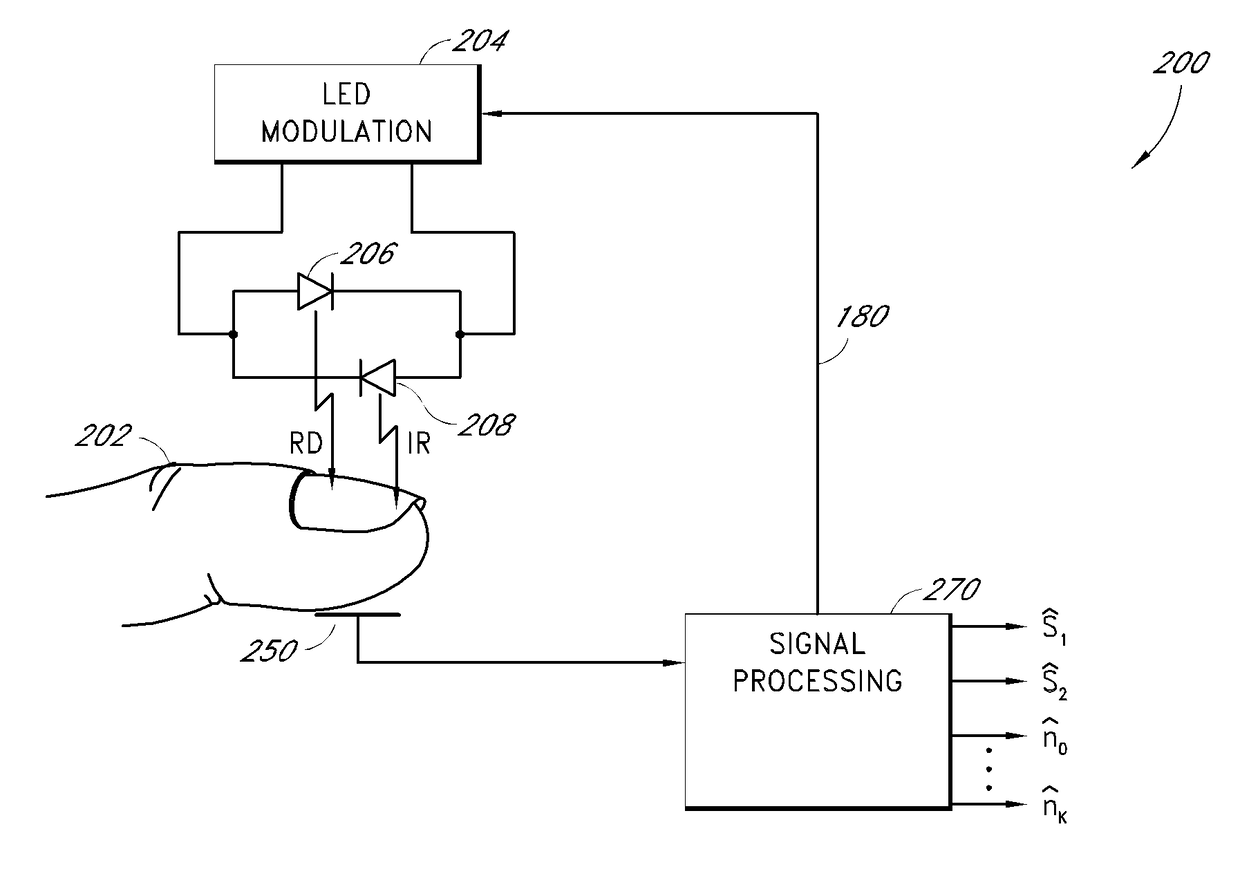
[0028]FIG. 1 shows a topology of a multi-channel measurement or communication system 100. The system 100 has a signal combiner 103 for combining one or more input signals S1 . . . SN into a composite signal and a signal separator 104 for separating the composite signal into one or more output signals Ŝ1 . . . ŜM The output signals Ŝ1 . . . ŜM can include estimates of the input signals S1 . . . SN. The input signals S1 . . . SN are corrupted by pre-combination distortion 101-102 respectively, and optionally, by combination distortion in the signal combiner 103. The combiner 103 combines the N input signals into a composite signal (or composite signals). The combiner 103 can combine signals by addition, subtraction, multiplication, division, modulation, non-linear processes, linear processes, estimation, combinations thereof, etc. The composite signal is provided through a communication channel to the separator 104. The composite signal is distorted by communication channel distortion...


PUM


Abstract

A method and an apparatus for separating a composite signal into a plurality of signals is described. A signal processor receives a composite signal and separates a composite signal into separate output signals. Feedback from one or more of the output signals is provided to a configuration module that configures the signal processor to improve a quality of the output signals. In one embodiment, calibration data from multiple calibration data sets is used to configure the demodulation of the composite signal into separate output signals.

Description

REFERENCE TO RELATED APPLICATIONS[0001]The present application is a continuation of U.S. application Ser. No. 14 / 836,635, filed Aug. 26, 2015, titled “METHOD AND APPARATUS FOR CALIBRATION TO REDUCE COUPLING BETWEEN SIGNALS IN A MEASUREMENT SYSTEM,” which is a continuation of U.S. application Ser. No. 13 / 526,376, filed Jun. 18, 2012, titled “METHOD AND APPARATUS FOR CALIBRATION TO REDUCE COUPLING BETWEEN SIGNALS IN A MEASUREMENT SYSTEM,” which is a continuation of U.S. patent application Ser. No. 11 / 871,636, filed Oct. 12, 2007, titled “METHOD AND APPARATUS FOR CALIBRATION TO REDUCE COUPLING BETWEEN SIGNALS IN A MEASUREMENT SYSTEM”, which claims priority benefit of U.S. Provisional Application No. 60 / 851,112, filed Oct. 12, 2006, titled “METHOD AND APPARATUS FOR CALIBRATION TO REDUCE COUPLING BETWEEN SIGNALS IN A MEASUREMENT SYSTEM”, the entire contents of which is hereby incorporated by reference.BACKGROUND OF THE INVENTIONField of the Invention[0002]The present invention relates to...

Claims


Application Information

Patent Timeline
Patent Type & Authority Applications(United States)
IPC IPC(8): A61B5/1455A61B5/1495A61B5/00
CPCA61B2562/0238A61B5/1495A61B5/1455A61B5/7228A61B5/14551A61B2560/0223
Inventor WEBER, WALTER M.AL-ALI, AMMARDIAB, MOHAMED K.LAMEGO, MARCELO M.
Owner MASIMO CORP
Why Eureka
Try Eureka