Lock-up device for torque converter

Active Publication Date: 2018-09-20
EXEDY
View PDF3 Cites 0 Cited by
  • Summary
  • Abstract
  • Description
  • Claims
  • Application Information

AI Technical Summary

Benefits of technology

The present patent aims to inhibit vibration in a lock-up device with multi-stage torsional characteristics. It achieves this by lowering stiffness and widening torsion angle in the torsional characteristics. The invention uses arc springs for both the first and second coil springs, which results in a more even distribution of the load on each coil spring and an alleviation of the stress on each pair of spring. This allows for a more effective reduction of stiffness and widening of torsion angle, leading to improved inhibition of vibration in the lock-up device.

Problems solved by technology

Therefore, a load acting on the outer peripheral side springs becomes relatively high, and this makes it difficult to effectively inhibit vibration by lowering stiffness in characteristics as much as possible.

Method used


Image

  • Lock-up device for torque converter
  • Lock-up device for torque converter
  • Lock-up device for torque converter

Examples


Embodiment Construction

Entire Configuration

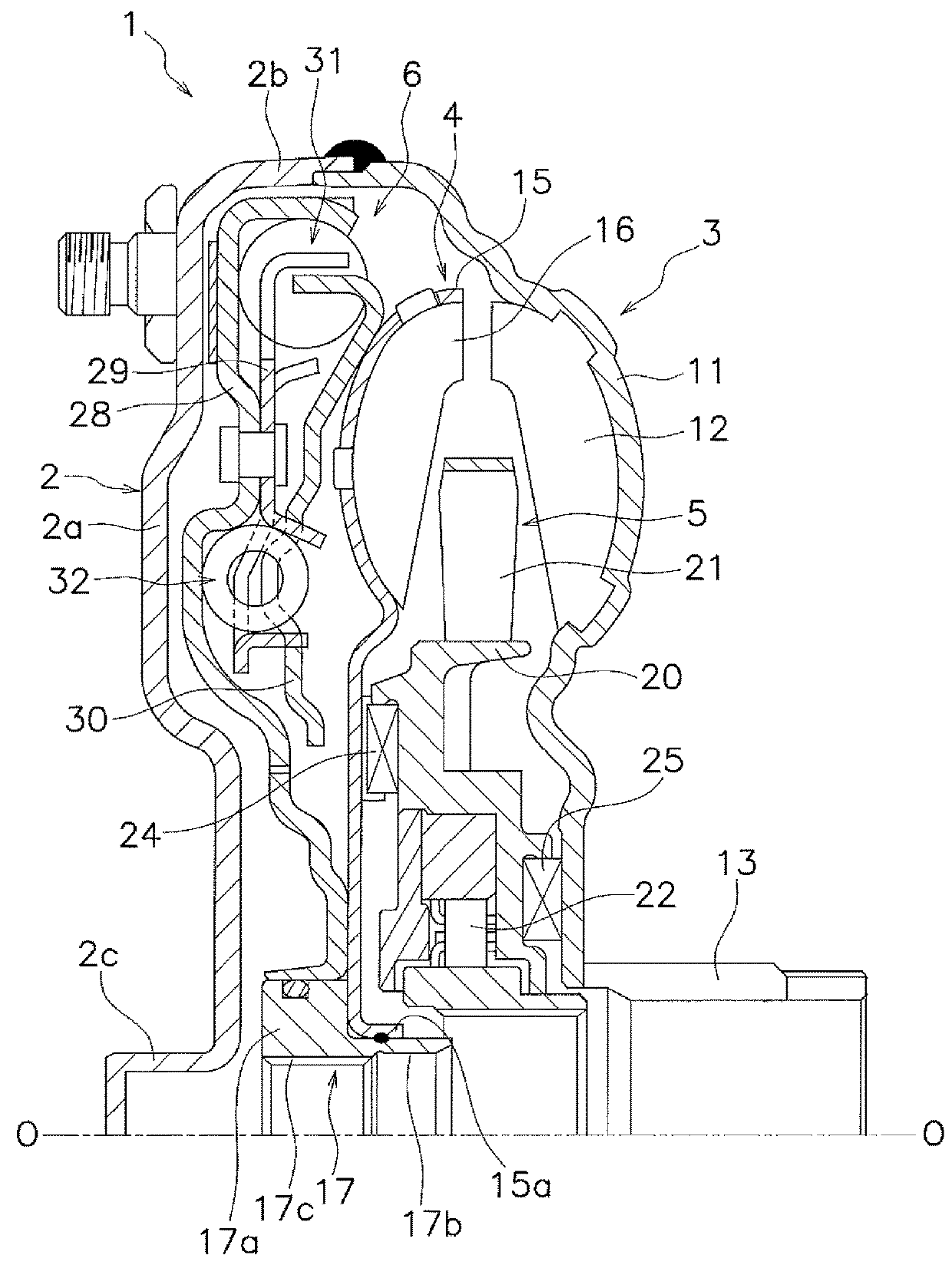
[0022]FIG. 1 is a schematic vertical cross-sectional view of a torque converter 1 including a lock-up device according to an exemplary embodiment of the present disclosure. The torque converter 1 is a device that transmits a torque from a crankshaft of an engine to an input shaft of a transmission. In FIG. 1, the engine (not shown in the drawing) is disposed on the left side, whereas the transmission (not shown in the drawing) is disposed on the right side. Line O-O depicted in FIG. 1 is a rotational axis of the torque converter 1.

[0023]The torque converter 1 includes a front cover 2, an impeller 3, a turbine 4, a stator 5 and a lock-up device 6. A fluid chamber having a torus shape is formed by the impeller 3, the turbine 4 and the stator 5.

[0024]The front cover 2 is a member into which a torque is inputted through a flexible plate (not shown in the drawings) . The front cover 2 is a member disposed on the engine side and includes a body 2a having a disc shape a...


PUM


Abstract

A lock-up device includes an input rotary member into which the torque is inputted and an output rotary member rotatable relatively to the input rotary member in a predetermined torsion angular range. The output rotary member outputs the torque. The lock-up device also includes a plurality of first coil springs coupling the input rotary member and the output rotary member. The plurality of first coil springs are actuated in an entirety of the torsion angular range. The lock-up device further includes a plurality of second coil spring pairs or sets on either an outer peripheral side or an inner peripheral side of the plurality of first coil springs so as to be actuated in parallel to the plurality of first coil springs. The two or more coil springs have different magnitudes of stiffness and are actuated in series.

Description

CROSS-REFERENCE TO RELATED APPLICATIONS[0001]This application is the U.S. National Phase of PCT International Application No. PCT / JP2015 / 082697, filed on Nov. 20, 2015. That application claims priority to Japanese Patent Application No. 2015-007593, filed Jan. 19, 2015. The contents of both applications are herein incorporated by reference in their entirety.BACKGROUNDTechnical Field[0002]The present disclosure relates to a lock-up device, particularly to a lock-up device for a torque converter, which transmits a torque and also absorbs and attenuates torsional vibration.Background Art[0003]Torque converters are often equipped with a lock-up device that directly transmits a torque from a front cover to a turbine. The lock-up device includes a clutch part into which a torque is inputted from a front cover, an output member fixed to a turbine, and a damper part disposed between the clutch part and the output member . The damper part includes a plurality of torsion springs and couples a...

Claims


Application Information

Patent Timeline
IPC IPC(8): F16F15/123F16H45/02
CPCF16F15/12366F16H45/02F16H2045/0231F16H2045/0278F16H2045/0205
Inventor MOTOTSUNE, KEN
Owner EXEDY
Why Eureka
Try Eureka