Systems and Methods for Spinal Stabilization

Inactive Publication Date: 2015-04-30
MIGHTY OAK MEDICAL INC
View PDF9 Cites 15 Cited by
  • Summary
  • Abstract
  • Description
  • Claims
  • Application Information

AI Technical Summary

Benefits of technology

[0032]In some forms, the spanning structure may include an outer member and an inner portion, wherein the bending stiffness may be selected by selection of the inner portion. The inner portion may be provided after securing the outer member with the anchors. The inner portion may be comprised of a plurality of inner components, and the bending stiffness may be selected by selecting a number of the components to be disposed within the outer member. The bending stiffness may be adjusted by removal or addition of the inner components. The bending stiffness may be adjusted by orientation of the inner portion relative to the outer member. At least one of the outer member and the inner portion may have eccentrically positioned regions of reduced cross-sectional area, and rotation of the regions provides a direction for lowered stiffness.
[0033]In some forms, the mechanical performance characteristic is a compression/expansion stiffness. The spanning structure may include a spring including a plurality of coil

Problems solved by technology

A surgeon's choices for spanning members are virtually limited to selecting either a rod or a bar, the length of the spanning member, and a cross-sectional dimension such as the rod's diameter.
Generally, however, these rods are limited in use to an entire system, and the deviation from the standard rod provided by these rods is not for mechanical behavior characteristics, instead being for cooperation with the other particularized features of a specific stabilization system.
It is also known that there are medical detriments that can arise from full immobilization.
For instance, it is know that a lack of pressure (i.e., stress, or weight) on bones can result in a decrease in density.
It is also suspected that intervertebral structures may suffer from a lack of use resulting from rigid systems.
Additionally, full immobilization can result in overstressing of adjacent areas, thus producing adjacent segment degeneration.
Over time, such friction results in wear to the components, which in turn may lead to reduced performance of the components, and revision surgery, or fragments of the components being free in the patient's body.
It is also known that implantation of an elastomeric/pol

Method used


Image

  • Systems and Methods for Spinal Stabilization
  • Systems and Methods for Spinal Stabilization
  • Systems and Methods for Spinal Stabilization

Examples


Example

[0101]Additional support for the varying embodiments depicted in these drawing figures is provided in the description below.

DETAILED DESCRIPTION

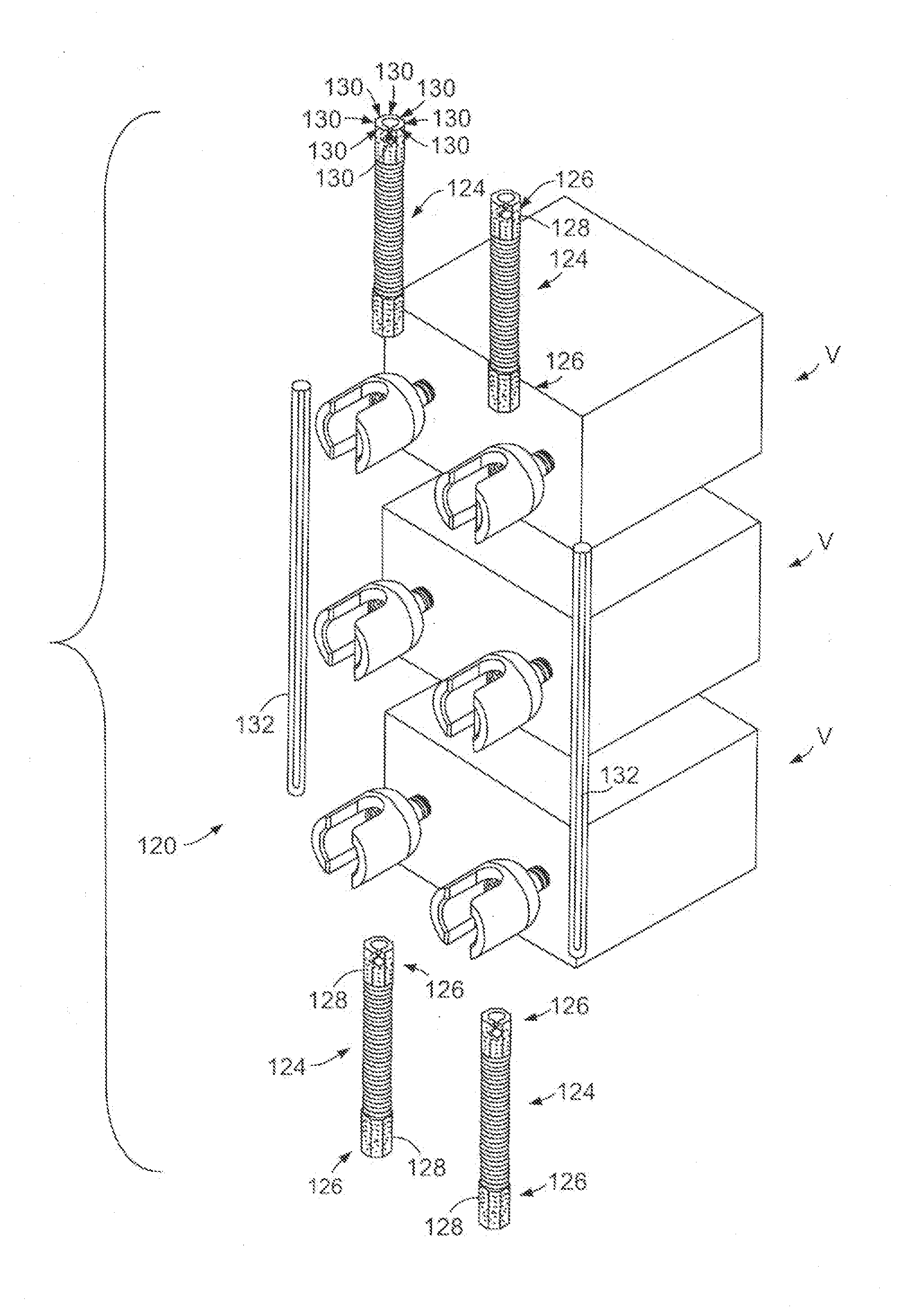
[0102]In accordance with aspects of the present invention, a plurality of forms and embodiments of spinal stabilization systems are depicted in FIGS. 1-47. In a variety of manners, these forms provide a user-surgeon with a range of choices for the motion that is permitted for spanning structures of the spinal stabilization system, the mechanical properties of the spanning structures including flexure, torsion, and / or compression and expansion, with linearly selectable mechanical properties, provide a surgeon with spanning structures that can provide a range of mechanical properties while being used with identical yokes of anchors, allow the surgeon to adjust the mechanical properties in situ, and allow the surgeon to adjust the mechanical properties post-operative without full-scale surgical revision.

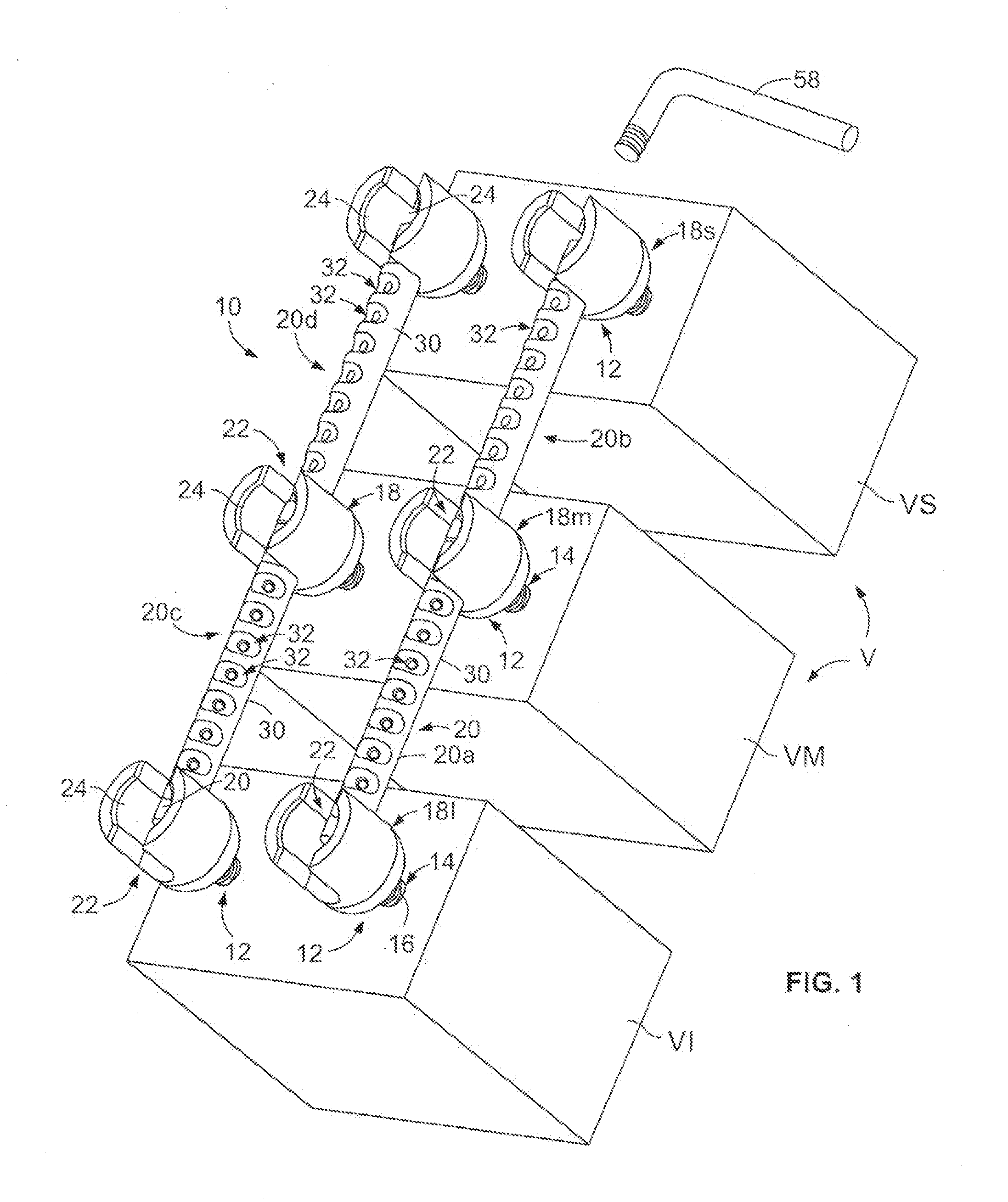
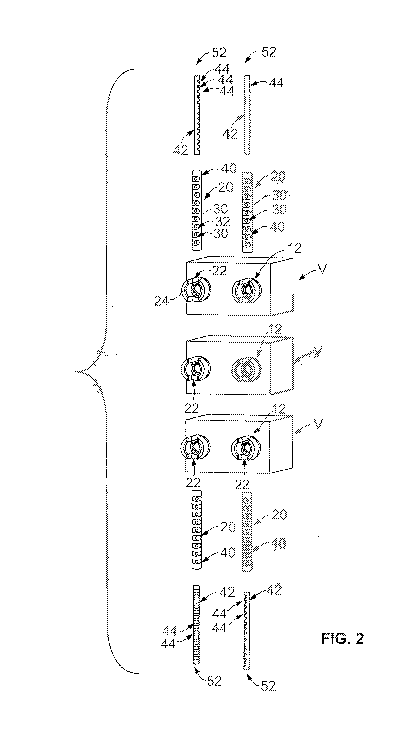
[0103]Referring to FIGS. 1-5, a first for...


PUM


Abstract

Spinal stabilization systems are disclosed having spanning portions extending between and securable to pedicle screw assemblies, the spanning portions have stiffness characteristics that may be variable or selectively adjustable, and/or have non-linear behavior with respect to force versus distortion. Additionally, the systems may utilize a plurality of spanning portions in which two or more of the spanning portions have different stiffness characteristics.

Description

CROSS-REFERENCE TO RELATED APPLICATIONS[0001]This application is a continuation-in-part of U.S. patent application Ser. No. 12 / 172,996, filed Jul. 14, 2008, which in turn claims priority to U.S. Provisional Patent Application No. 60 / 959,456 filed Jul. 13, 2008. These applications are all incorporated by reference herein in their entireties.FIELD OF THE INVENTION[0002]The invention relates to systems and methods for spinal stabilization and, in particular, to systems and methods allowing for variability and / or adjustability of the mechanical behavior of spinal stabilization system and, more particularly, to such systems and methods that allow a user to select or adjust the mechanical behavior of a spinal stabilization during implantation, as well as extra-corporeally after implantation.BACKGROUND OF THE INVENTION[0003]Spinal stabilization systems take a variety of forms. Typically, these systems would more generally be described as spinal immobilization systems as the intent is for r...

Claims


Application Information

Patent Timeline
IPC IPC(8): A61B17/70
CPCA61B17/7026A61B17/7028A61B17/7031A61B2017/00544A61B17/7032A61B17/7035A61B2017/00539A61B17/701A61B17/7004A61B17/7014A61B17/7046A61B17/705
Inventor FREY, GEORGEO'NEIL, CHARLESLAI, GEOFFRYDIN, RUSS
Owner MIGHTY OAK MEDICAL INC
Why Eureka
Try Eureka