Suspension device for non-steered driving wheel incorporating in-wheel motor

Inactive Publication Date: 2018-11-22
TOYOTA JIDOSHA KK
View PDF0 Cites 9 Cited by
  • Summary
  • Abstract
  • Description
  • Claims
  • Application Information

AI Technical Summary

Benefits of technology

The present patent text describes an improvement to a suspension device for non-steered driving wheels that reduces the change in steer angle when the wheel encounters longitudinal, road surface, or lateral forces. The technical effect of this improvement is better control and stability during driving.

Problems solved by technology

However, in a conventional suspension device for a wheel incorporating an in-wheel motor such as the suspension device described in the above-mentioned Japanese Patent Application Laid-open publication, a position of an principal elastic axis determined by an elastic vibration isolator member and a change in steered angle of the wheel about the principal elastic axis are not taken into consideration.
In particular, since a change in steered angle about an principal elastic axis in non-steered wheels cannot be prevented by steering or holding by a driver, the problem of steered angle change is significant in non-steered wheels, and further significant in non-steered driving wheels where a braking / driving force of the wheels changes.

Method used


Image

  • Suspension device for non-steered driving wheel incorporating in-wheel motor
  • Suspension device for non-steered driving wheel incorporating in-wheel motor
  • Suspension device for non-steered driving wheel incorporating in-wheel motor

Examples


first embodiment

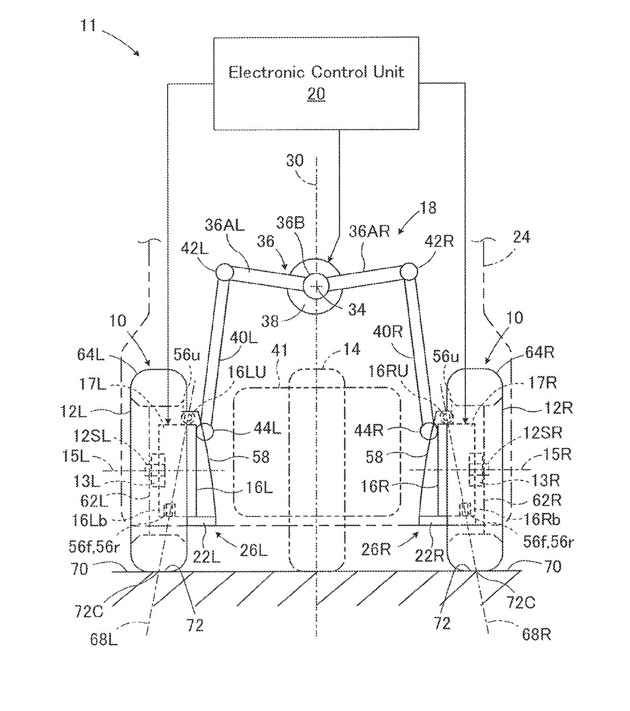
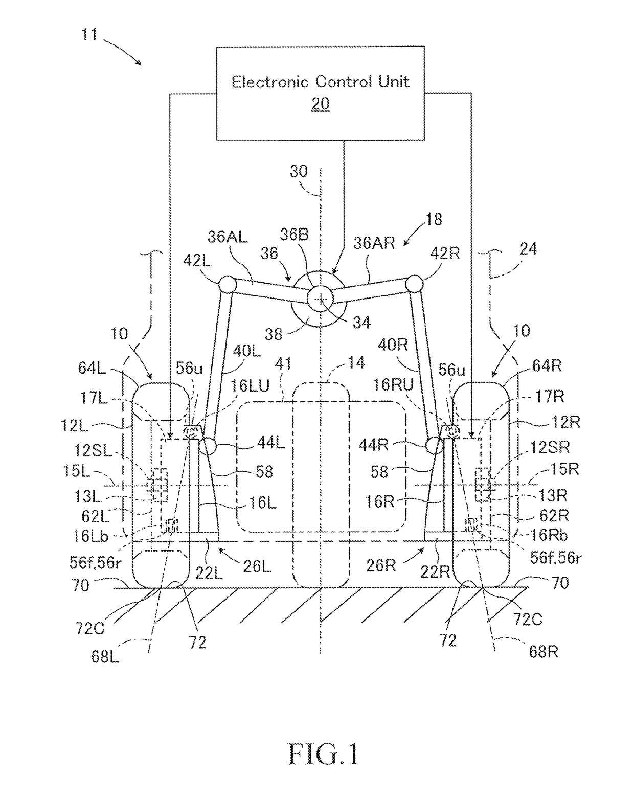
[0033]In FIGS. 1 to 3, a suspension device 10 according to a first embodiment of the present disclosure is applied to an automatic tilting vehicle 11, and is configured as a leading arm type suspension device. The vehicle 11 is a three-wheeled vehicle including a pair of front wheels 12L and 12R which are non-steered driving wheels, and a single rear wheel 14 which is a steered driven wheel. The front wheels 12L and 12R are spaced apart from each other in the lateral direction. Axles 12SL and 12SR of the front wheels 12L and 12R are rotatably supported by corresponding wheel carriers 16L and 16R via bearings 13L and 13R about rotation axes 15L and 15R, respectively. The automatic tilting vehicle 11 further includes a vehicle tilting device 18 and an electronic control unit 20. It should be noted that the rear wheel 14 may be a steered driving wheel or two wheels having a smaller tread than the front wheels.

[0034]The front wheels 12L and 12R are suspended from a vehicle body 24 by th...

second embodiment

[0053]FIGS. 4 and 5 are side and rear views, respectively of a main part of a right front wheel suspension device according to the second embodiment of the present disclosure. In FIGS. 4 and 5, the same members as those shown in FIGS. 2 and 3 are denoted by the same reference numerals as those denoted in FIGS. 2 and 3, respectively. This also applies to FIGS. 6 to 9 showing the third and fourth embodiments described later.

[0054]In the second embodiment, the suspension device 10 is configured as a double wishbone type suspension device including one upper arm 70R and two lower arms 72R and 74R. The upper arm 70R and the lower arms 72R and 74R substantially extend in the lateral direction. The upper arm 70R is pivotally supported on the vehicle body 24 at the inner end via a joint 70Ri and pivotally attached to the wheel carrier 16R at the outer end via a joint 70Ro. The lower arms 72R and 74R are pivotally supported on the vehicle body 24 at the inner ends thereof via joints 72Ri and...

third embodiment

[0059]FIGS. 6 and 7 are side and rear views, respectively of a main part of a right front wheel suspension device according to the third embodiment of the present disclosure.

[0060]In the third embodiment, the suspension device 10 is configured as a double wishbone type suspension device including two upper arms 80R and 82R and one lower arm 84R. The upper arms 80R and 82R and the lower arm 84R substantially extend in the lateral direction. The upper arms 80R and 82R are pivotally supported on the vehicle body 24 at the inner ends via the joints 80Ri and 82Ri, respectively, and are pivotally connected to the wheel carrier 16R via joints 80Ro and 82Ro at the outer ends. The lower arm 84R is pivotally supported on the vehicle body 24 at the inner end via a joint 84Ri and pivotally attached to the wheel carrier 16R at the outer end via a joint 84Ro.

[0061]As shown in FIG. 6, the joint 80Ro is positioned above and in front of the rotation axis 15R of the front wheel 12R, and the joint 82R...


PUM


Abstract

A suspension device for a non-steered driving wheel in which an in-wheel motor for driving the driving wheel is incorporated in a wheel carrier and which includes suspension arm pivotally supported on a vehicle body at one end and connected at the other end to the wheel carrier via at least two elastic bushing devices. A principal elastic axis which is determined by the at least two elastic bushing devices and extends vertically passes through a grounding area of the driving wheel.

Description

CROSS-REFERENCE TO RELATED APPLICATION[0001]The disclosure of Japanese Patent Application NO. JP2017-97418 filed on May 16, 2017 is incorporated by reference in its entirety.BACKGROUND1. Technical Field[0002]The present disclosure relates to a suspension device, and more particularly to a suspension device for a non-steered driving wheel incorporating an in-wheel motor.2. Description of the Related Art[0003]In a vehicle such as an electric vehicle having wheels that each incorporate an in-wheel motor, each in-wheel motor is housed in a housing and cooperates with the housing to form an in-wheel motor unit. A main part of the in-wheel motor unit is disposed radially inside a wheel member of the wheel together with a support member for rotatably supporting the wheel. A suspension device that suspends the wheel incorporating the in-wheel motor from a vehicle body includes a suspension arm that is pivotally supported on the vehicle body at one end so that the wheel can move up and down ...

Claims


Application Information

Patent Timeline
IPC IPC(8): B60G3/20B60K7/00
CPCB60G3/20B60K7/0007B60G2204/1482B60G2204/12B60G2200/182B60G15/062B60G2202/31B62K5/10B62K2005/001B60G7/008B60G15/00B60G15/068B60G2200/422B60G2200/14B60G2204/182B60G2204/30B60G2202/25B60G2300/50B60K2007/0038B60K2007/0092B60G3/14B60G2200/132B60G2200/446B60G2202/42B60G2204/148B60G2204/41B60G2204/422B60G2206/012B60G2206/16B60G2300/122B60G2300/45B62K5/05B62K5/08
Inventor KATO, YOSHIHISAADACHI, SATOSHI
Owner TOYOTA JIDOSHA KK
Why Eureka
Try Eureka