Particulate-Incorporating Attachment for a Drop Spreader

Active Publication Date: 2019-08-01
WADKINS JOE DENNIS
View PDF1 Cites 1 Cited by
  • Summary
  • Abstract
  • Description
  • Claims
  • Application Information

AI Technical Summary

Benefits of technology

[0022]In a further aspect of the present invention, a shield is attached to the mount bracket, the implement holder, and/or the brush/rake to reduce overspray of the particulates onto the operator of

Problems solved by technology

This standard method of infill installation is less than desirable, because of the time and labor re

Method used


Image

  • Particulate-Incorporating Attachment for a Drop Spreader
  • Particulate-Incorporating Attachment for a Drop Spreader
  • Particulate-Incorporating Attachment for a Drop Spreader

Examples


second embodiment

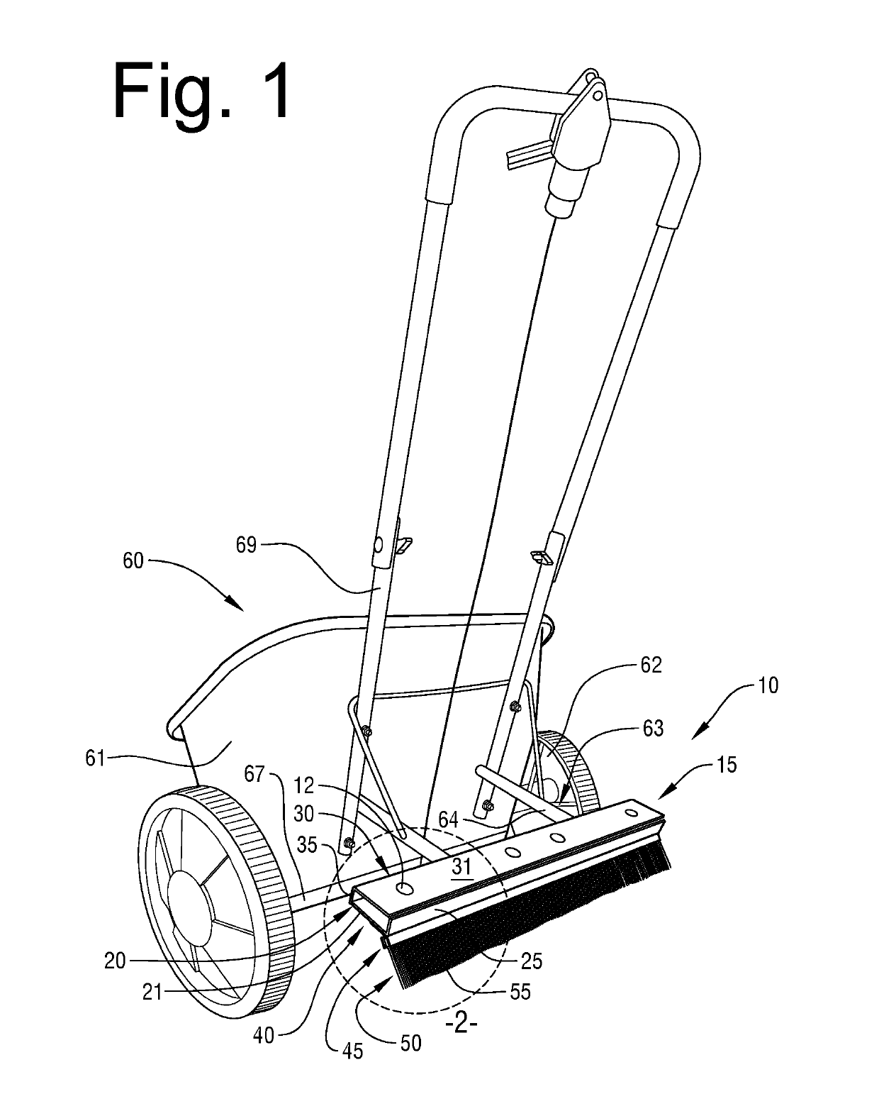
[0058]The proximal bracket portion 20 is configured with hole edges defining a set of holes 28 that correspond to the set of distal bracket holes 38. After insertion of the spreader rest brace 63 into the flange notches 36 (illustrated in FIG. 10, in the discussion of the second embodiment) the proximal bracket portion 20 is attached with fasteners 12, such as carriage bolts, to the distal bracket portion 30 via the aligned, corresponding sets of holes 28, 38 to form the completed mount bracket 15.

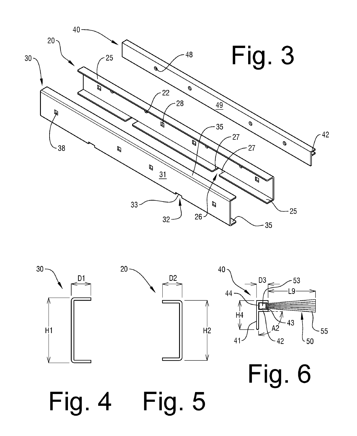
[0059]The implement holder 40 is a panel (preferably metal) extending substantially the length of the distal bracket portion 30 that attaches adjacent to the proximal bracket portion 20. (In another aspect, the implement holder 40 is optionally formed integrally with the proximal bracket portion 20.) The implement holder 40 may be attached to the outer side of the proximal bracket portion 20 before forming the completed mount bracket 15 or may be attached to the completed mount bracket 15....

third embodiment

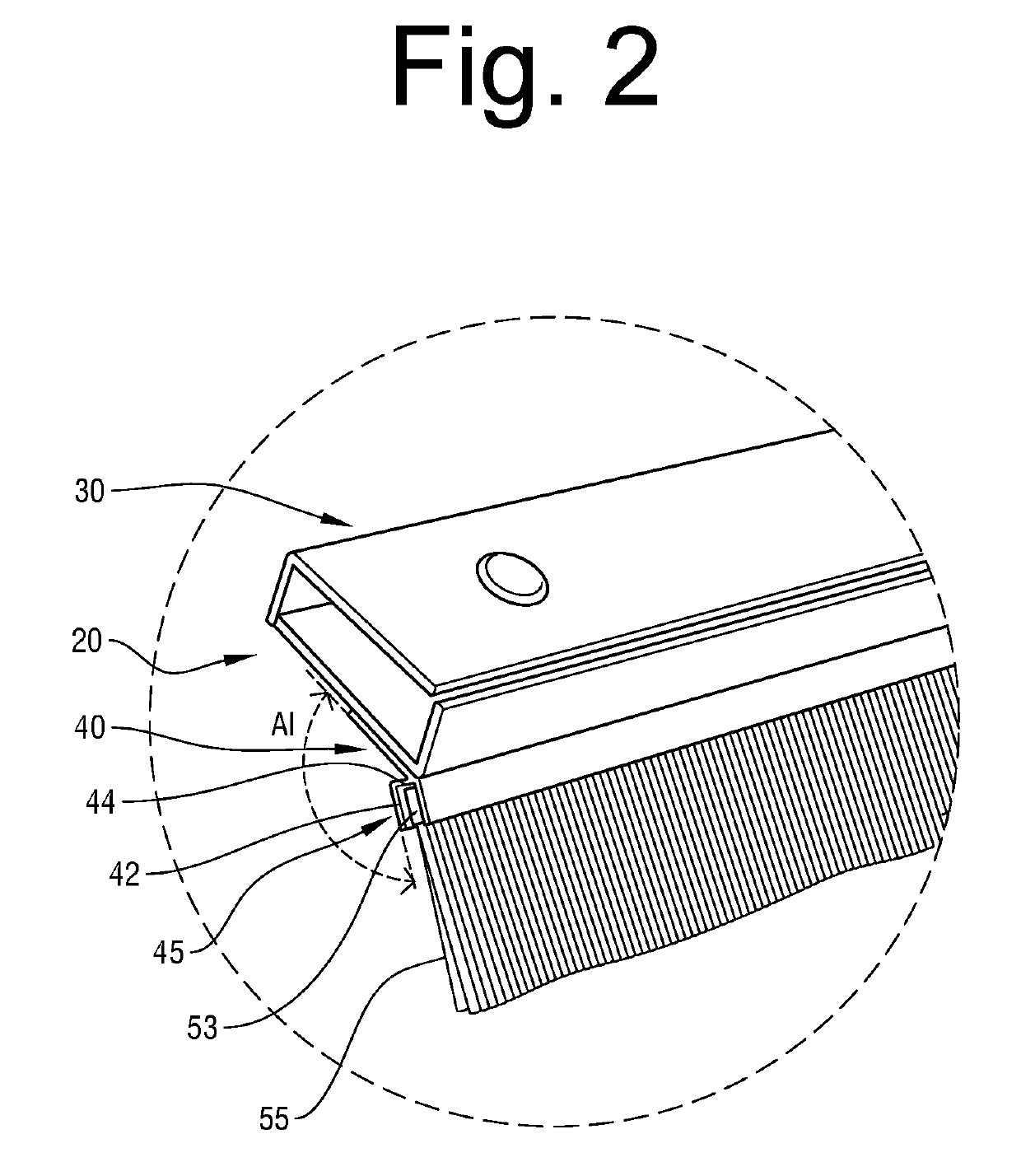
[0062]The implement holder 40 supports the channel 45 into which the rake / brush 50 is received, as seen in FIG. 11. The channel preferably runs substantially the length of the implement holder 40, but multiple channel portions that each extend a portion of the length of the implement holder 40 may optionally be used to hold the rake / brush 50. In the aspect shown in FIG. 11, the rake / brush 50 is removable from the implement holder 40 and is replaceable when worn. In another aspect, the rake / brush 50 is non-removable from the channel 45 of the implement holder 40, but, instead, is fixedly attached via a securing means, such as by glue or adhesives or by screws, bolts or other hardware. In another aspect, shown in FIGS. 13-14, the implement holder 40 and the rake / brush 50 are formed integrally. In the aspects in which the rake / brush 50 is fixedly attached within the implement holder channel 45 or formed integrally with the implement holder 40, if the rake / brush 50 becomes worn and unus...

first embodiment

[0067]As in the first embodiment, the distal bracket upper flange 35 is configured with a pair of notches 36 defined by notch edges 37, with the notches 36 sized and spaced to receive the rest brace extending arms 64, as seen in FIG. 10. In addition, due to the overlapping of the proximal bracket upper flange 25 with the distal bracket upper flange 35, the proximal bracket upper flange 25 comprises a pair of notches 26 defined by notch edges 27 that correspond to the pair of distal bracket upper flange notches 36 and that also receive the rest brace extending arms 64.

[0068]In one aspect of the invention, the distal bracket upper flange notch edges 37 may extend past the substantially ninety-degree bend that is created during fabrication of the bend between the upper flange 35 and the panel 31. The continuation of notch edges 37 past the bend and into the panel 31 portion creates a portion of the notch 36 that extends beyond the bend, notch extension 32 defined by notch edges 33, as ...


PUM


Abstract

A particulate-incorporating attachment for a drop spreader is provided that includes a two-portion mount bracket, an implement holder, and a rake/brush and optionally includes wheels. The bracket portions are connected to form a mount bracket over the rest brace of the drop spreader. The mount bracket mounts the implement holder, which supports the rake/brush in a suitable position to assist in the incorporation of infill material into the space between the grass tufts of synthetic turf or to assist in the incorporation of other dropped particulates into synthetic or natural turf or onto the ground.

Description

CROSS-REFERENCE TO RELATED APPLICATIONS[0001]This application is a continuation-in-part of co -pending U.S. patent application Ser. No. 15 / 464,315 filed on Mar. 20, 2017, which will issue on Apr. 9, 2019 as U.S. Pat. No. 10 / 252,288 and which is incorporated herein in its entirety.FIELD OF INVENTION[0002]This invention relates generally to manual outdoor turf equipment and, more particularly, to a particulate -incorporating attachment for a manual drop spreader suitable for use in incorporating particles dispensed by the drop spreader, particularly during the filling of synthetic turf spaces with infill material.BACKGROUND[0003]Replacing grass with artificial or synthetic turf provides several advantages, such as greatly reducing the need for lawn maintenance and eliminating the use of water for lawn irrigation. Synthetic turf is typically fabricated with an upward-facing synthetic green grass face formed by tufts of grass and a downward-facing backing or understructure that supports...

Claims


Application Information

Patent Timeline
IPC IPC(8): B05C11/02B05C19/00E01C13/08E01C19/20
CPCB05C11/023B05C19/008E01C13/08E01C19/2005B05C19/04E01C19/4866E01C19/4873E01C19/15
Inventor WADKINS, JOE DENNIS
Owner WADKINS JOE DENNIS
Why Eureka
Try Eureka