Process and device for aerating suspensions

Inactive Publication Date: 2008-12-04
ANDRITZ AG
View PDF4 Cites 2 Cited by
  • Summary
  • Abstract
  • Description
  • Claims
  • Application Information

AI Technical Summary

Benefits of technology

[0009]If the solids suspension is diluted to a consistency of some 0.6-1.4%, particularly 0.8-1.3%, before entering the secondary cells, the flotation efficiency can be increased.
[0020]Furthermore, it has provided advantageous to interpose at least two washers into the primary cells loop.

Problems solved by technology

In the processes known, however, some disadvantages occur in selective flotation.
If, for example, attempts are made to target the removal of fillers by making certain changes to the process, this always results in a drop in the efficiency of printing ink removal, which leads to a need for additional changes in gas loading, adjustments to the raw material fluctuations, and changes in throughput.
Furthermore, if the overflow quantity is increased in order to raise the removal rate of mineral substances, the fibre loss rises in equal proportion to this, which leads to greater expense for disposal and raw materials required.

Method used


Image

  • Process and device for aerating suspensions
  • Process and device for aerating suspensions
  • Process and device for aerating suspensions

Examples


Embodiment Construction

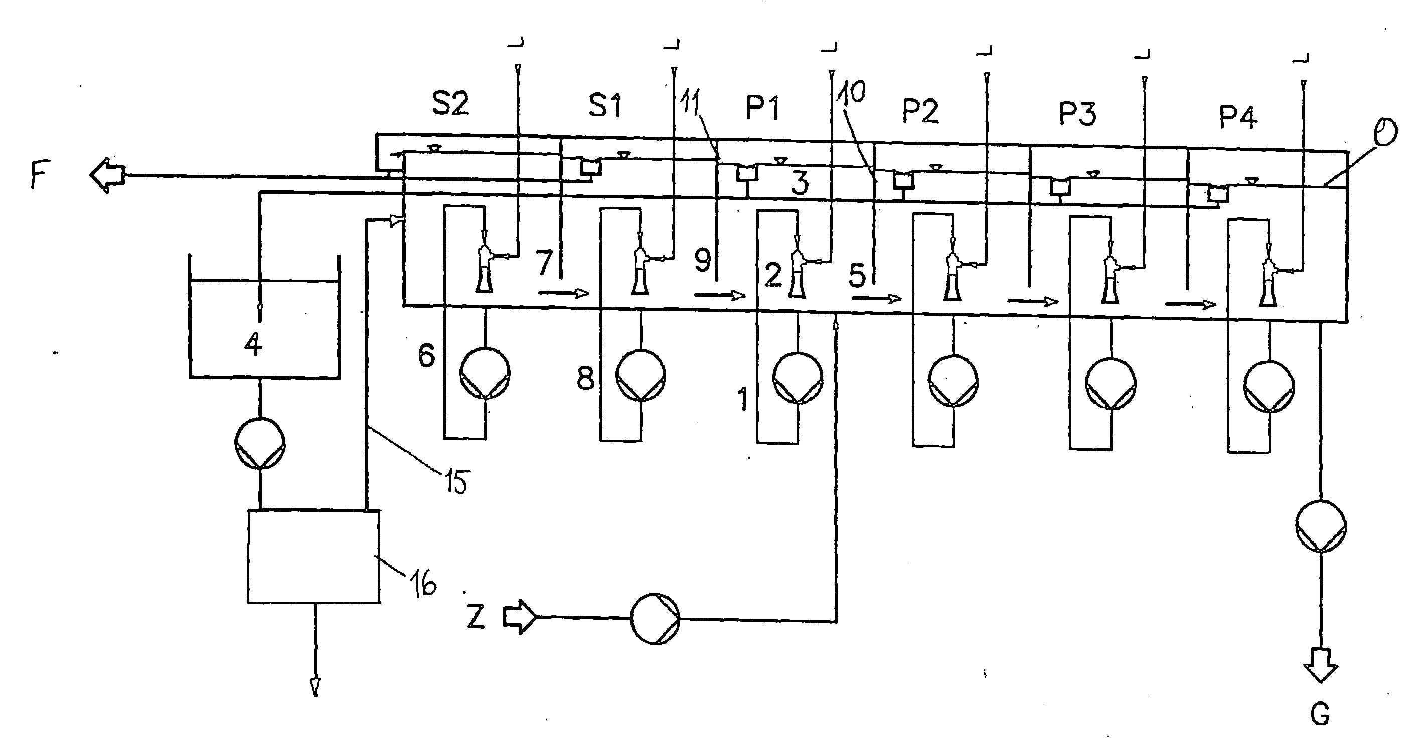
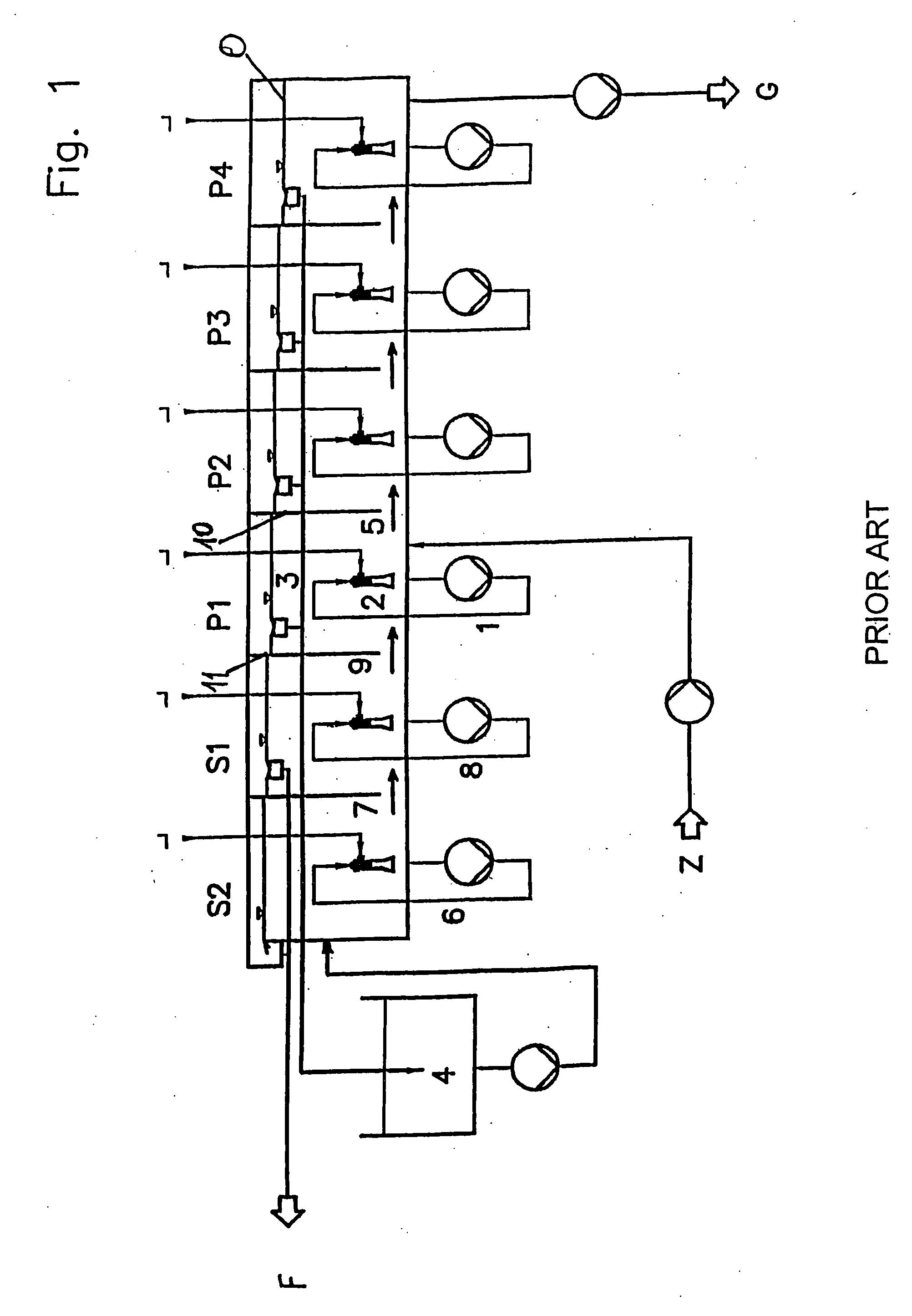
[0031]FIG. 1 is a schematic diagram of a flotation plant according to the state of the art having a primary stage with four primary cells, P1, P2, P3 and P4, and a secondary stage with two secondary cells, S1 and S2. The flow of pulp suspension Z is brought into the first primary cell P1 at a suitable point. The aeration bubbles are generated inside this cell via internal loop 1, which is disconnected from the feed, by the injector 2 drawing in suspension from the bottom of the cell in a liquid line and air from an air line Land mixing it for injection into the suspension in the same cell. The entire flotation plant is largely filled with suspension, on the surface o of which a foam forms which contains as much as possible of the mineral substances and ink particles to be removed by flotation. The accept flow cleaned in primary cell P1 to remove ink and impurities is transferred to the second primary cell P2 through an opening 5 located at the base of the dividing wall 10. There and...


PUM

PropertyMeasurementUnit
Fractionaaaaaaaaaa
Fractionaaaaaaaaaa
Fractionaaaaaaaaaa

Abstract

The disclosure relates to a process and device for aerating suspensions, particularly to flotate them, for example in deinking of pulp suspensions which includes a primary and secondary stage. In order to improve ash removal, a washing process is interposed between the primary and secondary stages.

Description

RELATED APPLICATION[0001]This application is a division of pending U.S. application Ser. No. 10 / 761,866 filed Jan. 21, 2004 entitled “Process and Device for Aerating Suspensions”, the benefit of which is claimed under 35 U.S.C. 120, the disclosure of which is incorporated by reference, and which claims priority under 35 U.S.C. 119 of Austrian Patent application A89 / 2003 filed Jan. 24, 2003.BACKGROUND OF THE INVENTION[0002]The invention relates to a process for aerating suspensions, particularly to flotate them, for example in deinking of pulp suspensions, with one or more stages and / or cells, where each stage / cell has its own separate liquid loop. In addition, the invention relates to a device for implementing the process.[0003]A process of this type is known, for example, from EP 1 124 001 A2, where the individual flotation stages can also be designed according to U.S. Pat. No. 4,255,262, EP 0 243 690, DE 31 20 202, or U.S. Pat. No. 6,208,549, for example.[0004]Processes of this ty...

Claims


Application Information

Patent Timeline
IPC IPC(8): B03D1/14B03D1/00B03D1/02D21B1/32D21D5/18D21F1/70
CPCB03D1/02D21B1/327D21D5/18D21F1/70B03D1/1462B03D1/1468B03D1/1431B03D1/24B03D1/1406Y02W30/64
Inventor GABL, HELMUTH
Owner ANDRITZ AG
Why Eureka
Try Eureka