Suction pick-up head

Inactive Publication Date: 2001-11-20
JOULIN MICHEL
View PDF10 Cites 2 Cited by
  • Summary
  • Abstract
  • Description
  • Claims
  • Application Information

AI Technical Summary

Benefits of technology

Thus, instead of causing all of the closure members of those compartments which are not in register with an article to be picked up to move simultaneously, provision is made to ensure that these compartments close in cascade, such that the instantaneous flow rate required is considerably reduced, thereby making it possible to reduce or even eliminate the buffer volume that has been necessary in prior devices. In addition, air flow inside the pick-up head is channeled by the partitioning, so that dust sucked in during pick-up is progressively entrained to the turbine from which it can then be ejected.
In an advantageous version of the invention, the partitioning comprises a manifold having branches disposed vertically in register with rows of compartments, the branches of the manifold being interconnected via connections in series or in parallel. Thus, in each branch of the manifold, the compartments are connected in series and the pick-up head is easily adapted to particular operating conditions by making corresponding series or parallel connections between the various branches of the manifold.
According to another advantageous feature of the invention, the pick-up head has walls forming a leakproof box around the manifold, the suction device is connected to the box, the manifold has a suction orifice opening out to the inside of the box and an exhaust orifice opening out to the outside of the box, and respective shutters are associated with the suction orifice and the exhaust orifice. Thus, the volume lying between the manifold and the walls of the box serves as a buffer volume whereby faster operation of the pick-up head is obtained without increasing the size thereof.

Problems solved by technology

However, to provide sufficient lifting force for the articles to be handled, it is necessary to cause the suction turbines to operate in a mode that provides a large amount of suction but at a small flow rate that does not make it possible simultaneously to raise a large number of closure members.
This implies not only that the pick-up head needs to be large in size, but also that it needs to be heavy, both of which needs constitute major drawbacks for a moving structure.
In addition, such suction through all of those compartments which are not in register with articles to be picked up causes a large amount of dust to be sucked up, which dust is subsequently deposited inside the box, where it piles up and impedes proper operation of the pick-up head.
In addition, sudden decompression of both the box and the buffer volume when the articles are put down gives rise to a loud noise which degrades working conditions for the operators of the pick-up system.

Method used


Image

  • Suction pick-up head
  • Suction pick-up head

Examples


Embodiment Construction

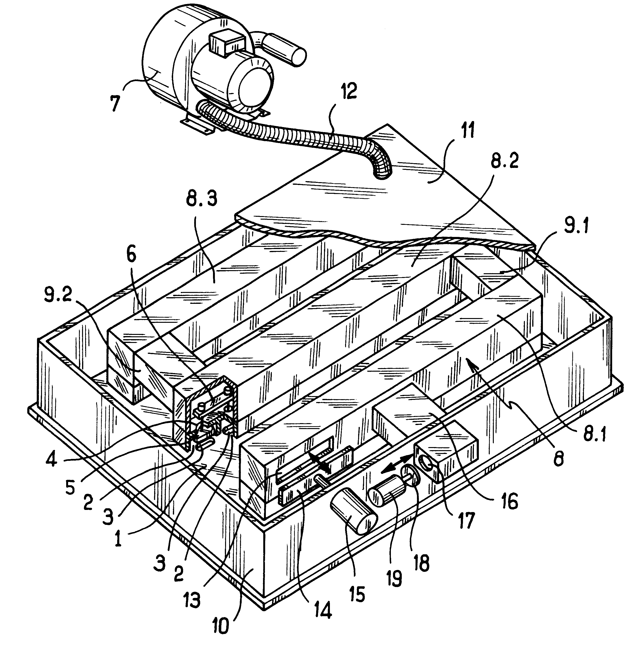
With reference to FIG. 1, the pick-up head comprises, in conventional manner, a soleplate 1 supporting rows of compartments 2, of which only two can be seen in the cutaway view of the figure. Each compartment 2 has a bottom orifice 3 opening out through the bottom face of the soleplate, and a top orifice 4 fitted with a moving closure member 5. In the embodiment shown, the closure member 5 is a valve member fixed to a rod passing through the top orifice 4 and associated with a guide member 6. In the embodiment shown, the pick-up head has only three rows of compartments 2, although in practice this number is not limiting.

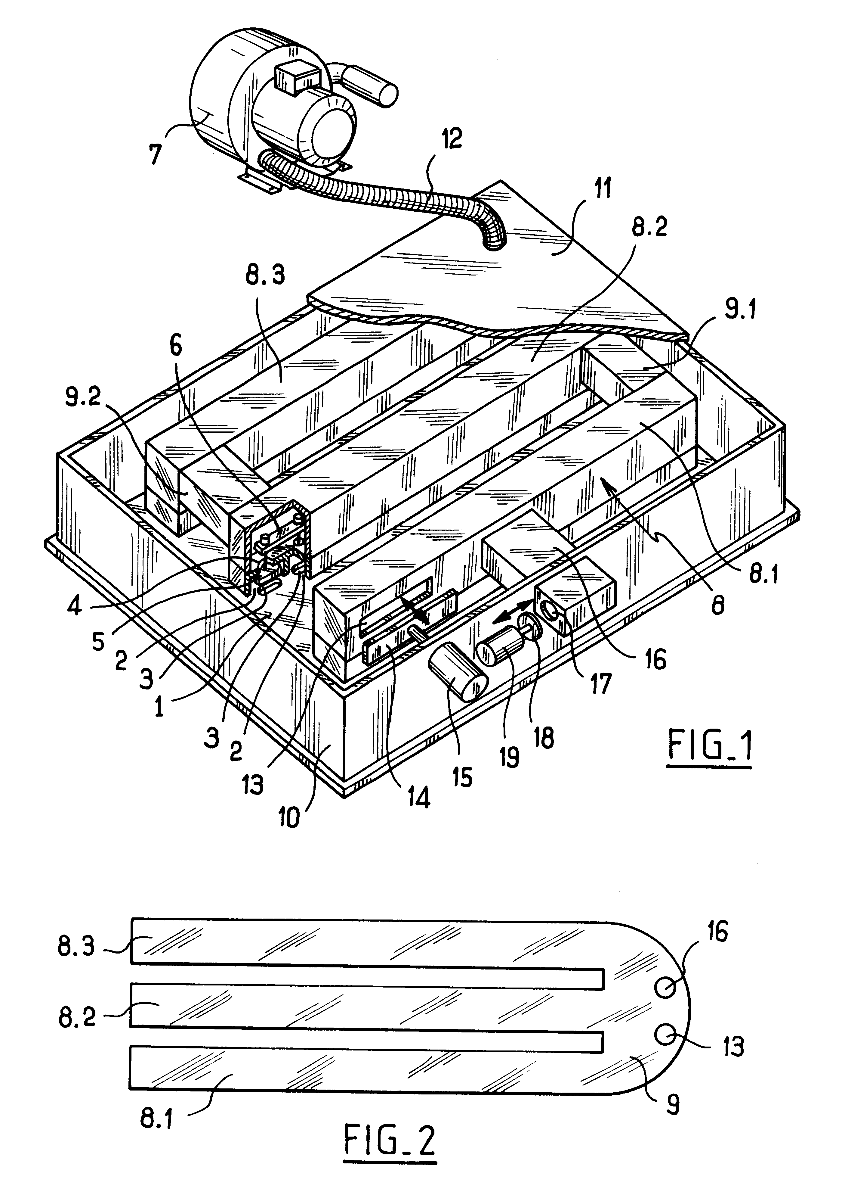
In accordance with the invention, the pick-up head has partitioning enabling at least some of the top orifices 4 of the compartment 2 to be connected in series relative to the suction device 7. In the embodiment shown, the partitioning comprises a manifold given overall reference 8 and having three branches respectively referenced 8.1, 8.2, and 8.3 and disposed in re...


PUM


Abstract

A suction pick-up head is disclosed having a soleplate supporting rows of compartments and connection devices for putting the compartments into communication with a suction device. The connection device includes partitioning ensuring that at least a portion of the compartments are connected in series or parallel relative to the suction device.

Description

The present invention relates to a pick-up head operating by suction.Systems are known for picking up and carrying material such as planks, sheet metal plates, or similar materials. Such systems comprise a structure mounted to move along a frame and including a pick-up head that operates by suction.In known systems, the suction pick-up head comprises a box connected to a suction device, generally a turbine, carried by the frame of the system. The box of the pick-up head has a soleplate supporting rows of independent compartments each having a bottom orifice opening out in the bottom face of the soleplate and a top orifice fitted with a moving closure member mounted in the compartment to enable the top orifice to be closed when the bottom orifice is not obstructed by an article to be picked up and the suction is sufficient to suck up the valve member. When the bottom orifice of the compartment is obstructed by an object to be picked up, the valve member remains open and the suction i...

Claims


Application Information

Patent Timeline
IPC IPC(8): B65G47/91
CPCB65G47/91
Inventor JOULIN, MICHEL
Owner JOULIN MICHEL
Why Eureka
Try Eureka