

Absorbent article
- Summary
- Abstract
- Description
- Claims
- Application Information
AI Technical Summary
Benefits of technology
Problems solved by technology
Method used
Image

Examples
first embodiment
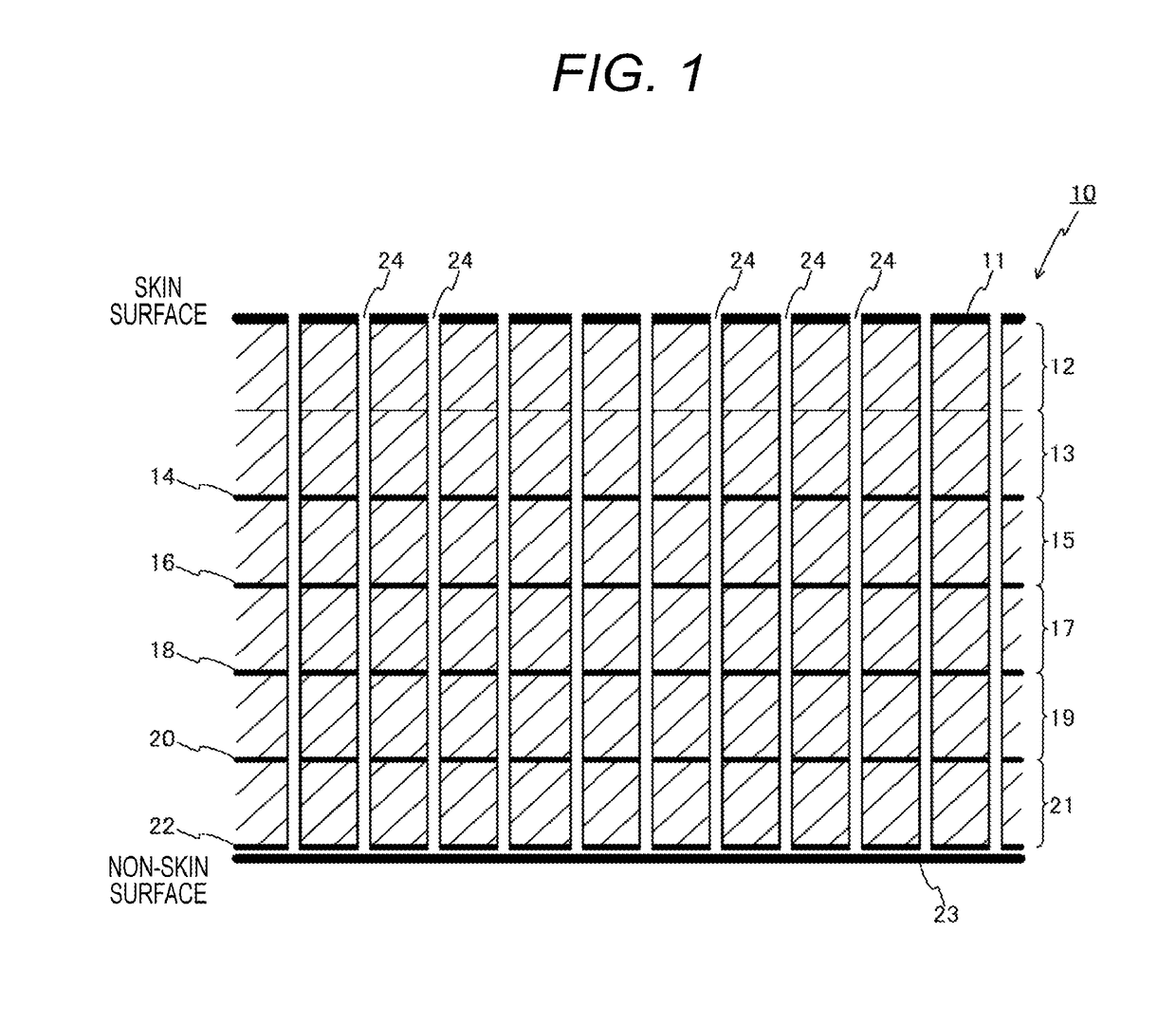
[0023]FIG. 1 is a conceptual diagram illustrating a configuration of an absorbent article 10 according to a first embodiment of the present invention. Hereinafter, the absorbent article 10 will be described with reference to FIG. 1. FIG. 1 illustrates a cross section of the absorbent article 10. Hereinafter, the absorbent article 10 will be described assuming an incontinence pad for men as an example.
[0024]The absorbent article 10 includes a surface sheet layer 11, a first pulp layer 12, a second pulp layer 13, a third pulp layer 15, a fourth pulp layer 17, a fifth pulp layer 19, and a sixth pulp layer 21 sequentially laminated in order from a skin surface side.
[0025]The surface sheet layer 11 is water-disintegrable paper serving as a skin surface when the absorbent article 10 is attached to a human body. Here, “water-disintegrability” refers to a property that entangled fibers are rapidly separated from one another by a water flow having a predetermined flow rate, and each separate...
second embodiment
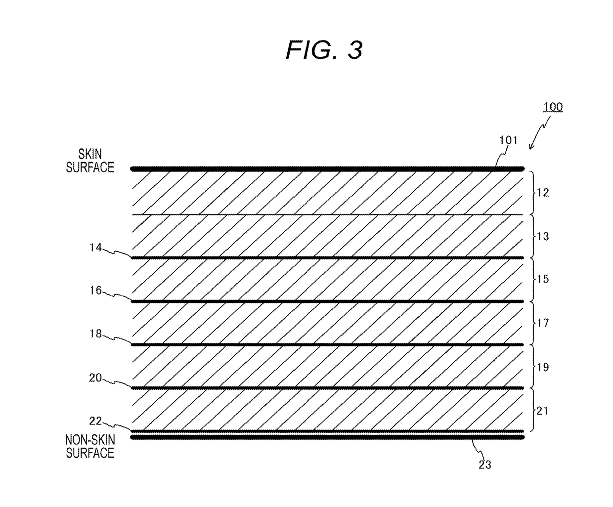
[0080]FIG. 3 is a conceptual diagram illustrating a configuration of an absorbent article 100 according to a second embodiment of the present invention. FIG. 3 is different from FIG. 1 in that the surface sheet layer 11 is changed to a surface sheet layer 101, and the holes 24 are eliminated.
[0081]The surface sheet layer 101 is different from the surface sheet layer 11 in that the surface sheet layer 101 is embossed and a water repellent agent is not applied to the surface sheet layer 101, and is similar to the surface sheet layer 11 in the other points.
[0082]In the absorbent article 100, at least the surface sheet layer 101 is embossed, and a regular shape is imparted. Note that embossing may be applied to any one or all of a first pulp layer 12 to a sixth pulp layer 21 and a back sheet layer 23.
[0083]As an embossed pattern formed on the surface sheet layer 101, for example, embossed patterns illustrated in FIGS. 4(a) to 4(h) are conceivable. Each of FIGS. 4(a) to 4(h) illustrates ...
third embodiment
[0102]FIG. 5 is a conceptual diagram illustrating a configuration of an absorbent article 200 according to a third embodiment of the present invention. FIG. 5 is different from FIG. 1 in that the first pulp layer 12 is changed to a first pulp layer 201, and the surface sheet layer 11 is eliminated.
[0103]The first pulp layer 201 is subjected to water repellent finish by applying a water repellent agent to a surface layer portion serving as a skin surface when the absorbent article 200 is attached to a human body. The surface layer portion of the first pulp layer 201 to which a water repellent agent has been applied is referred to as a water repellent surface layer portion 202. The first pulp layer 201 is similar to the first pulp layer 12 in the other points.
[0104]As described above, since the surface layer portion of the first pulp layer 201 is a skin surface, when the absorbent article 200 is worn, the soft surface layer portion of the first pulp layer 201 comes into contact with t...
PUM
| Property | Measurement | Unit |
|---|---|---|
| Length | aaaaa | aaaaa |
| Shape | aaaaa | aaaaa |
| Strength | aaaaa | aaaaa |
Abstract
Description
Claims
Application Information