Watertight device of heading machine for passing in and out cavity
A technology of water stop device and access hole, which is applied in shaft equipment, shaft lining, tunnel lining, etc. It can solve the problems of unreasonable and effective use of enclosure structure, internal space of multi-working wells, and impact of construction operations, so as to reduce construction cost. cost, extended working time, and convenient control
- Summary
- Abstract
- Description
- Claims
- Application Information
AI Technical Summary
Problems solved by technology
Method used
Image
Examples
Embodiment 1
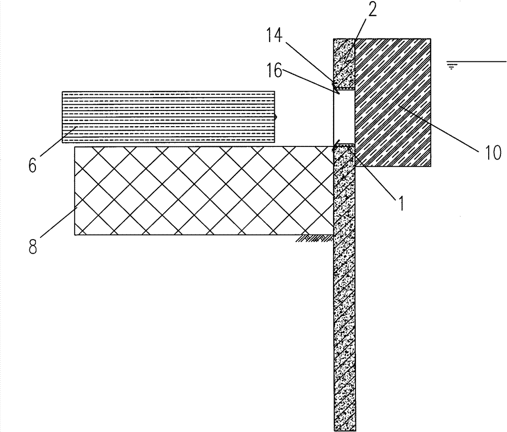
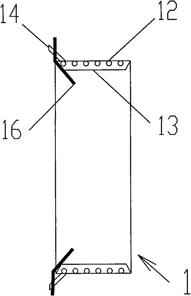
[0048] see figure 1 with figure 2 The utility model relates to a water stop device for entering and exiting holes of a boring machine, and the water stop device is used for working wells. The working well is provided with a protective structure, and the protective structure has a door opening. The water stop device includes a freezing pipe 12 for injecting refrigerant, and part or all of the freezing pipe 12 is placed around the opening of the door. On the inner wall, the enclosure structure is also provided with a grouting pipe communicating with the space enclosed by the freezing pipe.
[0049] The working well is divided into an originating well and a receiving well. In this embodiment, the working well is an originating well. The outer end of the enclosure structure 2 is provided with a reinforced foundation 10 .
[0050] In this embodiment, a ring 11 for positioning the boring machine is fixed inside the door opening, and the inner wall of the door opening is the inner ...
Embodiment 2
[0072] The difference between this embodiment and embodiment 2 is that please refer to Figure 6-8 , the working well is a receiving well. The entry and exit hole water stop device of the boring machine is a water stop device for the entry and exit of the boring machine, and the side of the freezing pipe 12 away from the enclosure structure 2 is provided with a sealing door 4 . The door closure 4 is fixed at the door opening of the enclosure structure 2 through the door sealing support structure 5 for blocking the door opening. Image 6 Shown is a structural schematic diagram of the situation where the freezing pipe 12 is arranged at the rear of the inner wall of the door opening of the enclosure structure 2 . Figure 7 Shown is a structural schematic diagram of the situation where part of the freezing pipe 12 is arranged in the door opening of the enclosure structure 2 . Figure 8 Shown is a structural schematic diagram of the case where the longitudinal width of the freezi...
Embodiment 3
[0074] Please refer to Figure 6-Figure 8 , this kind of water-stopping device for the entry and exit of the excavating machine, the water-stopping device is used for the working well, the working well is provided with an enclosure structure 2, the inner side of the enclosure structure 2 is provided with a lining structure 3, and the inner The lining structure 3 has a door opening, the water stop device 1 includes a freezing pipe 12 for injecting refrigerant, part or all of the freezing pipe 12 is placed around the inner wall of the door opening, and the lining structure 3 is also provided with A grouting pipe 14 communicating with the space enclosed by the freezing pipe 12 .
[0075] In this embodiment, the working well is a receiving well. The entry and exit hole water stop device of the boring machine is a water stop device for the entry and exit of the boring machine, and the side of the freezing pipe 12 away from the enclosure structure 2 is provided with a sealing door ...
PUM
 Abstract
Description
Claims
Application Information
 - R&D
- Intellectual Property
- Life Sciences
- Materials
- Tech Scout
- Unparalleled Data Quality
- Higher Quality Content
- 60% Fewer Hallucinations
Browse by: Latest US Patents, China's latest patents, Technical Efficacy Thesaurus, Application Domain, Technology Topic, Popular Technical Reports.
© 2025 PatSnap. All rights reserved.Legal|Privacy policy|Modern Slavery Act Transparency Statement|Sitemap|About US| Contact US: help@patsnap.com


