
Foundation pile and construction method thereof

A construction method and a technology for foundation piles, which are applied in the directions of foundation structure engineering, sheet pile wall, construction, etc., can solve the problems of high cost, insufficient lateral gripping force of the pipe body 11, weak fixed bonding force, etc.

Inactive Publication Date: 2012-07-04
DEHAN INTELLECTUAL TECH
View PDF0 Cites 0 Cited by
  • Summary
  • Abstract
  • Description
  • Claims
  • Application Information

AI Technical Summary

Problems solved by technology

[0007] 1. Time-consuming and costly:
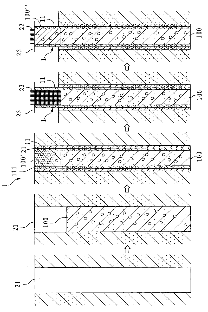
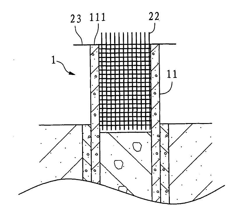
[0008] Because when the pipe body 11 of the existing implantable foundation pile 1 is implanted into the implant hole 21, part of the cement slurry 100 will flow upward from the gap between the pipe body 11 and the implant hole 21, And mix with the soil around the implant hole 21 and then flow back into the pipe body 11 through the top edge 111 of the pipe body 11, and in the area of ​​the pipe body 11 adjacent to the top edge 111 (i.e. the aforementioned pile head) solidified into poor-quality concrete 100' mixed with soil. Therefore, after excavating the surrounding soil on the outer periphery of the top of the existing implanted foundation pile 1 to expose the pile head, it is necessary to spend more man-hours to remove the pile head. The poor-quality concrete 100' in the pipe body 11 causes the time cost and labor cost spent on the construction of the existing implanted foundation pile 1 to be relatively high
[0009] 2. The anchoring effect of the reinforcement cage 22 is not good:
[0010] Since the reinforcement cage 22 is only suspended in the pipe body 11 by the reinforcement bars 23 whose two ends straddle the top edge 111 of the pipe body 11, the reinforcement cage 22 is only supported by the reinforcement cage 23 at its central part. weight, but the fixed bonding force at its two ends is rather weak, and it cannot be anchored firmly and reliably. In addition, the concrete 100” that covers and combines the implanted foundation pile 1 and the steel cage 22 is only formed on the pipe Only between the inner surface of the body 11 and the steel cage 22, there is no lateral gripping force, so when the superstructure of the implanted foundation pile 1 is subjected to lateral or axial forces such as wind force or earthquake force, it will be easy to Cause the reinforcement cage 22 to produce lateral displacement or even loosening and other phenomena and then lead to disasters
[0011] 3. The lateral gripping force of the pipe body 11 is also insufficient:
[0013] This shows that the above-mentioned existing foundation piles and construction methods thereof obviously still have inconvenience and defects in use, and need to be further improved urgently.
In order to solve the above-mentioned problems, the relevant manufacturers have tried their best to find a solution, but no suitable design has been developed for a long time, and there is no suitable structure and method for general products and methods to solve the above-mentioned problems. This is obviously a problem that relevant industry players are eager to solve

Method used


Image

  • Foundation pile and construction method thereof
  • Foundation pile and construction method thereof
  • Foundation pile and construction method thereof

Examples


Embodiment Construction

[0044] For further elaborating the technical means and effects that the present invention takes to reach the intended invention purpose, below in conjunction with accompanying drawing and preferred embodiment, to its specific implementation, structure, step, method for the foundation pile proposed according to the present invention and construction method thereof Features and their functions are described in detail below.

[0045] Below in conjunction with accompanying drawing and embodiment the present invention is described in detail:

[0046] see Figure 5 , Image 6 Shown are a sectional view and a partially enlarged sectional view of the first preferred embodiment of the foundation pile of the present invention, respectively. The foundation pile 3 of the first preferred embodiment of the present invention includes a top cover 31, a surrounding wall 32 extending downward from the periphery of the top cover 31, and a surrounding wall 32 that is spaced from the top cover 3...


PUM


Abstract

The invention relates to a foundation pile and a construction method thereof. The foundation pile comprises a top cover, an encircling wall which extends downwards from the periphery of the top cover, a division plate which is connected to the encircling wall in a mode of being spaced with the top cover, two positioning holes which pass through the encircling wall in opposite directions, and a plurality of pressure relief holes which pass through the encircling wall, wherein an accommodating space is formed by matching the encircling wall with the top cover; and the division plate divides theaccommodating space into a first accommodating part positioned between the top cover and the division plate and a second accommodating part spaced with the first accommodating part. The invention also discloses the construction method of the foundation pile. The division plate prevents cement slurry from flowing into the first accommodating part, the pressure relief holes can avoid the piping phenomenon, and the transverse bond stress of the foundation pile can be better improved after the cement slurry is solidified.

Description

technical field [0001] The invention relates to a foundation pile and a construction method thereof, in particular to a foundation pile and a construction method thereof which can effectively reduce costs and improve lateral gripping force. Background technique [0002] When constructing large or high-rise buildings, if the ground strength is insufficient or the soft soil layer is encountered, it is often necessary to use foundation piles driven into the ground to transfer the load of the upper building to the soil bearing layer or a harder ground to increase the building capacity. The safety and stability of the material structure. [0003] Furthermore, environmental protection awareness has increased in recent years, so the construction of foundation piles also needs to consider the impact of noise, vibration and air pollution generated during construction on the surrounding environment. Therefore, implanted foundation piles have received more and more attention in recent ...

Claims


Application Information

Patent Timeline
Patent Type & Authority Patents(China)
IPC IPC(8): E02D5/50
Inventor 李胜男
Owner DEHAN INTELLECTUAL TECH
Learn More