Electronic device

Inactive Publication Date: 2019-08-01
MURATA MFG CO LTD
View PDF0 Cites 3 Cited by
  • Summary
  • Abstract
  • Description
  • Claims
  • Application Information

AI Technical Summary

Benefits of technology

[0008]Preferred embodiments of the present invention provide electronic devices each including a plurality of coil antennas used in a plurality of respective systems, which enables checki

Problems solved by technology

However, in the configuration in which both of the two coil antennas are provided on the first surface side, if the two coil antennas are arranged so as not to interfere with each other, the position, size, shape, and other characteristics of the coil antennas are restricted, which may lower the degree of freedom of design.
However, because the coil antenna for NFC is disposed on the second surface (front surface) side of the electronic

Method used


Image

  • Electronic device
  • Electronic device
  • Electronic device

Examples


first preferred embodiment

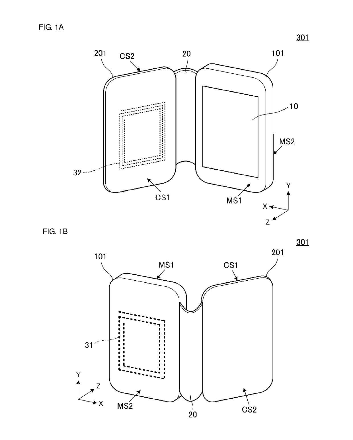
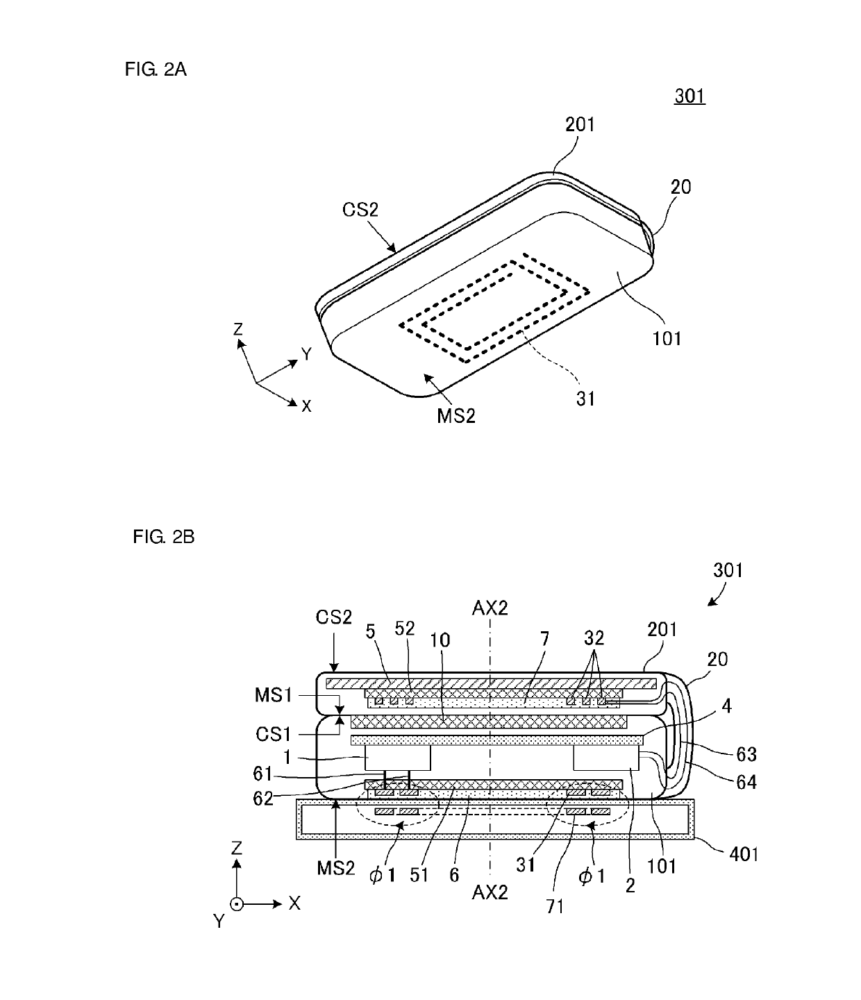
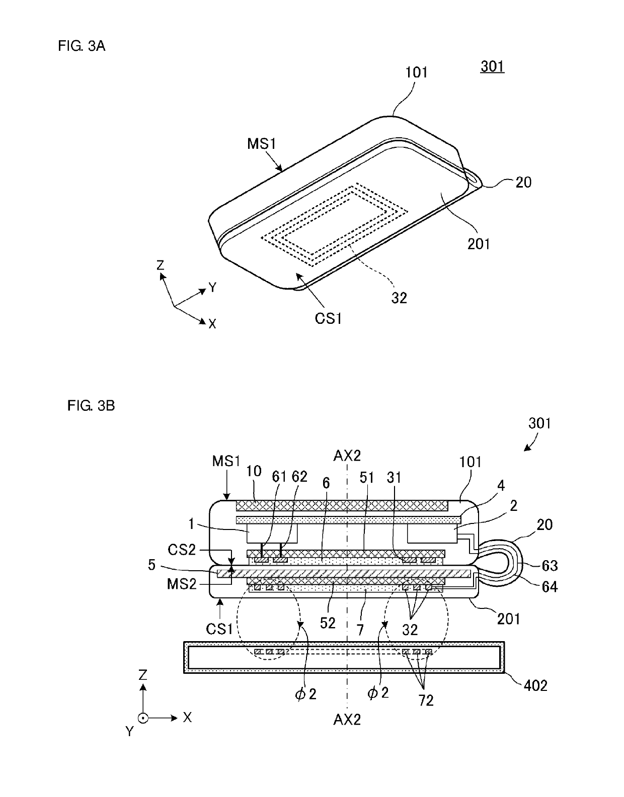
[0041]FIG. 1A is an exterior perspective view of an electronic device 301 according to a first preferred embodiment of the present invention, and FIG. 1B is an external perspective view of the electronic device 301 from a viewpoint different from FIG. 1A. FIG. 2A is an exterior perspective view illustrating the electronic device 301 in a first state, and FIG. 2B is a sectional view of the electronic device 301 in the first state. FIG. 3A is an exterior perspective view illustrating the electronic device 301 in a second state, and FIG. 3B is a sectional view of the electronic device 301 in the second state. FIG. 4 is a circuit diagram of the electronic device 301.

[0042]In FIGS. 1A, 1B, 2A, and 3A, a first coil antenna 31 and a second coil antenna 32 are illustrated by broken lines in order to clarify the structure of the electronic device 301. In FIGS. 2B and 3B, the thickness of each portion is illustrated in an exaggerated manner. The same applies to sectional views in the followin...

second preferred embodiment

[0068]In a second preferred embodiment of the present invention, an exemplary electronic device in which the second system circuit and the second coil antenna are not directly connected to each other will be described.

[0069]FIG. 5A is an exterior perspective view of an electronic device 302 according to the second preferred embodiment, and FIG. 5B is an external perspective view of the electronic device 302 from a viewpoint different from FIG. 5A. FIG. 6 is a sectional view of the electronic device 302 in the first state. FIG. 7A is a sectional view of the electronic device 302 in the second state, and FIG. 7B is a sectional view of the electronic device 302 viewed from a different direction in the second state. FIG. 8 is a circuit diagram of the electronic device 302.

[0070]In FIGS. 5A and 5B, the first coil antenna 31 and the second coil antenna 32 are illustrated by broken lines in order to clarify the structure of the electronic device 302. In FIG. 8, the first coil antenna 31 is...

third preferred embodiment

[0077]In a third preferred embodiment of the present invention, an example in which the configuration of the second main body portion is different from the above-described preferred embodiments will be described.

[0078]FIG. 9 is an exterior perspective view of an electronic device 303 according to the third preferred embodiment in the first state.

[0079]The electronic device 303 is different from the electronic device 301 according to the first preferred embodiment in that the electronic device 303 includes a second main body portion 203. The remaining configuration of the electronic device 303 is the same or substantially the same as the electronic device 301. Hereinafter, only portions that are different from the electronic device 301 will be described.

[0080]The area of the second main body portion 203 according to the present preferred embodiment (the area of the first surface CS1 and the second surface CS2) is smaller than the area of the display 10. The second main body portion 2...


PUM


Abstract

An electronic device includes a first main body portion including first and surfaces, and a second main body portion connected to the first main body portion. The first main body portion includes a display close to the first surface, and a first coil antenna. The second main body portion includes a second coil antenna. The first coil antenna is closer to the second surface than to the first surface. The second coil antenna is disposed in the second main body portion. The electronic device is switchable between a first state in which the second main body portion does not overlap the second surface when using the electronic device in the first system, and a second state in which the second main body portion overlaps the second surface when using the electronic device in the second system.

Description

CROSS REFERENCE TO RELATED APPLICATIONS[0001]This application claims the benefit of priority to Japanese Patent Application No. 2016-225883 filed on Nov. 21, 2016 and is a Continuation Application of PCT Application No. PCT / JP2017 / 039085 filed on Oct. 30, 2017. The entire contents of each of these applications are hereby incorporated herein by reference.BACKGROUND OF THE INVENTION1. Field of the Invention[0002]The present invention relates to an electronic device, and more particularly, to an electronic device for use in a plurality of systems.2. Description of the Related Art[0003]An electronic device including a coil antenna for a short-range wireless communication (NFC: Near Field Communication) system and a coil antenna for a wireless power transmission system is known.[0004]For example, International Publication No. 2014 / 167881 discloses an electronic device in which a coil antenna for NFC and a coil antenna for wireless power transmission are both provided on a first surface (...

Claims


Application Information

Patent Timeline
IPC IPC(8): G06F1/16H02J50/10H01Q1/24H02J7/02
CPCG06F1/1683H02J50/10G06F1/1681H01Q1/243H02J7/025H05K9/00H02J50/12H02J50/70G06F1/1656G06F1/1698G06F1/1616H04M2250/04H04M1/185H04M1/0214H02J50/005H01Q21/28H01Q7/06H01Q1/52
Inventor TENNO, NOBUYUKIIKUNO, TOSHINORI
Owner MURATA MFG CO LTD
Why Eureka
Try Eureka