Apparatus and method for determining blood flow velocity

Active Publication Date: 2018-04-12
KONINKLJIJKE PHILIPS NV
View PDF0 Cites 0 Cited by
  • Summary
  • Abstract
  • Description
  • Claims
  • Application Information

AI Technical Summary

Benefits of technology

[0020]There is also provided, according to a second aspect of the invention, a controller for the apparatus of the first aspect. The controller comprises a communications interface for enabling communication between the controller and ultrasound transmitter and between the controller and an ultrasound receiver; and a processing unit. The processing unit is arranged to output a control signal to an ultrasound transmitter to cause the ultrasound transmitter to emit an ultrasound pulse; receive a measurement

Problems solved by technology

However; these parameters are difficult to measure, either invasively or non-invasively, and there is no widely-accepted “gold standard” measurement technique.
However; these methods have several drawbacks.
They cannot be used continuously, which makes them unsuitable for monitoring the effect of an intervention on the hemodynamic status of a patient.
Furthermore, they provide a result which is an average over many heartbeats, meanin

Method used


Image

  • Apparatus and method for determining blood flow velocity
  • Apparatus and method for determining blood flow velocity
  • Apparatus and method for determining blood flow velocity

Examples


Example

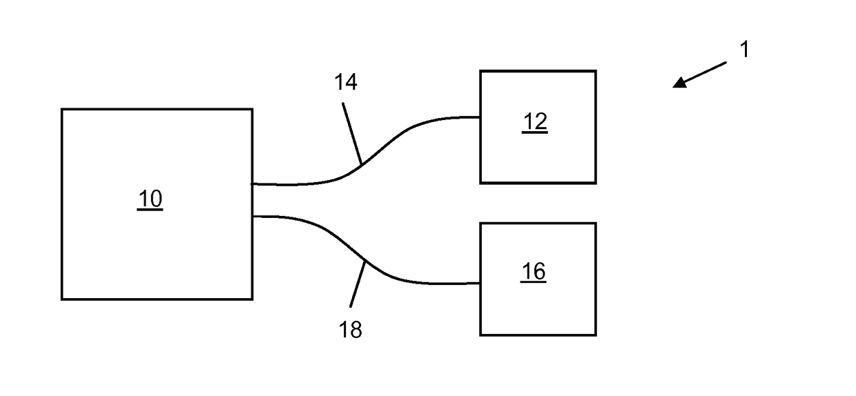
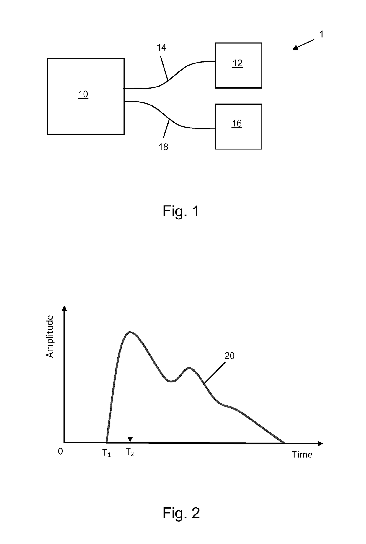
[0027]FIG. 1 shows an apparatus 1 for measuring the velocity of blood flowing in a blood vessel of a subject according to an embodiment of the invention. The apparatus 1 comprises a controller 10 that is in communication with a transmitter 12 via a communications link 14 and that is in communication with a receiver 16 via a communications link 18. The communications links 14, 16 may be any combination of wired or wireless. In embodiments in which both communications links are wired, the length of the wires is effective to permit the transmitter 12 and the receiver 16 to be arranged on a subject such that a blood vessel in which it is desired to measure blood flow velocity is located between the transmitter 12 and the receiver 16. For example, in an embodiment in which the apparatus 1 is for measuring the velocity of blood flowing in the descending aorta, the transmitter 12 is configured for placement on or near the neck of the subject and the receiver 16 is configured for placement ...


PUM


Abstract

Apparatus and method comprising an ultrasound transmitter, for placement at a first location on the body of a subject, to emit an ultrasound pulse; an ultrasound receiver, for placement at a second location on the body, to detect an emitted ultrasound pulse; and a controller in communication with the transmitter and receiver. The controller causes an ultrasound pulse to be emitted by the transmitter; receives a measurement signal from the receiver; determines, based on the received measurement signal, a time of arrival at the receiver, T1 s of a first part of the emitted ultrasound pulse; determines, based on the received measurement signal, a time of arrival at the receiver, T2, of a second part of the ultrasound pulse; and calculates, using T1 and T2, a flow velocity of blood in a blood vessel between the first location and the second location.

Description

TECHNICAL FIELD OF THE INVENTION[0001]The invention relates to an apparatus and method for determining blood flow velocity, and in particular to an apparatus and method for measuring the velocity of blood flowing in a blood vessel of a subject.BACKGROUND TO THE INVENTION[0002]From a clinical point-of-view, the best indication of the hemodynamic status of a patient is provided by the amount of blood the heart pumps, per beat (stroke volume) and per minute (cardiac output). However; these parameters are difficult to measure, either invasively or non-invasively, and there is no widely-accepted “gold standard” measurement technique.[0003]Stroke volume and cardiac output can be measured invasively, e.g. using thermo-dilution or indicator-dilution techniques. However; these methods have several drawbacks. They cannot be used continuously, which makes them unsuitable for monitoring the effect of an intervention on the hemodynamic status of a patient. Furthermore, they provide a result whic...

Claims


Application Information

Patent Timeline
IPC IPC(8): A61B8/06A61B8/00A61B8/08A61B8/15A61B5/024A61B5/00
CPCA61B8/065A61B8/4236A61B8/4477A61B8/5223A61B8/54A61B8/15A61B5/024A61B5/725A61B8/58A61B8/56A61B8/06
Inventor LAMBERT, NICOLAASKROON, BARTKOLEN, ALEXANDER FRANCISCUSMATHEW, DENNYBEZEMER, RICK
Owner KONINKLJIJKE PHILIPS NV
Why Eureka
Try Eureka